For electrical engineers, designing the Supervisory Control and Data Acquisition system (SCADA) for an electrical substation can be a daunting task, if not confusing with the different ways you can connect various Intelligent Electronic Devices (IED’s) based on protocols each device supports. This article serves to help you understand this system so you can design one as well.
SCADA system implements automation using two distinct functionalities. The first one is the supervisory control of the system and the second one is the data acquisition. Let’s begin with the data acquisition.
Data Acquisition
Breaker control relays, transformer monitoring devices, protection relays are just a few devices in a substation that monitor and gather data on the systems. Storing this data on the device itself serves no purpose. Considering the fact that most substations are automated and are left unmanned, transmitting this information to power grid control centers for control or engineering offices for system analysis, is the way to go.
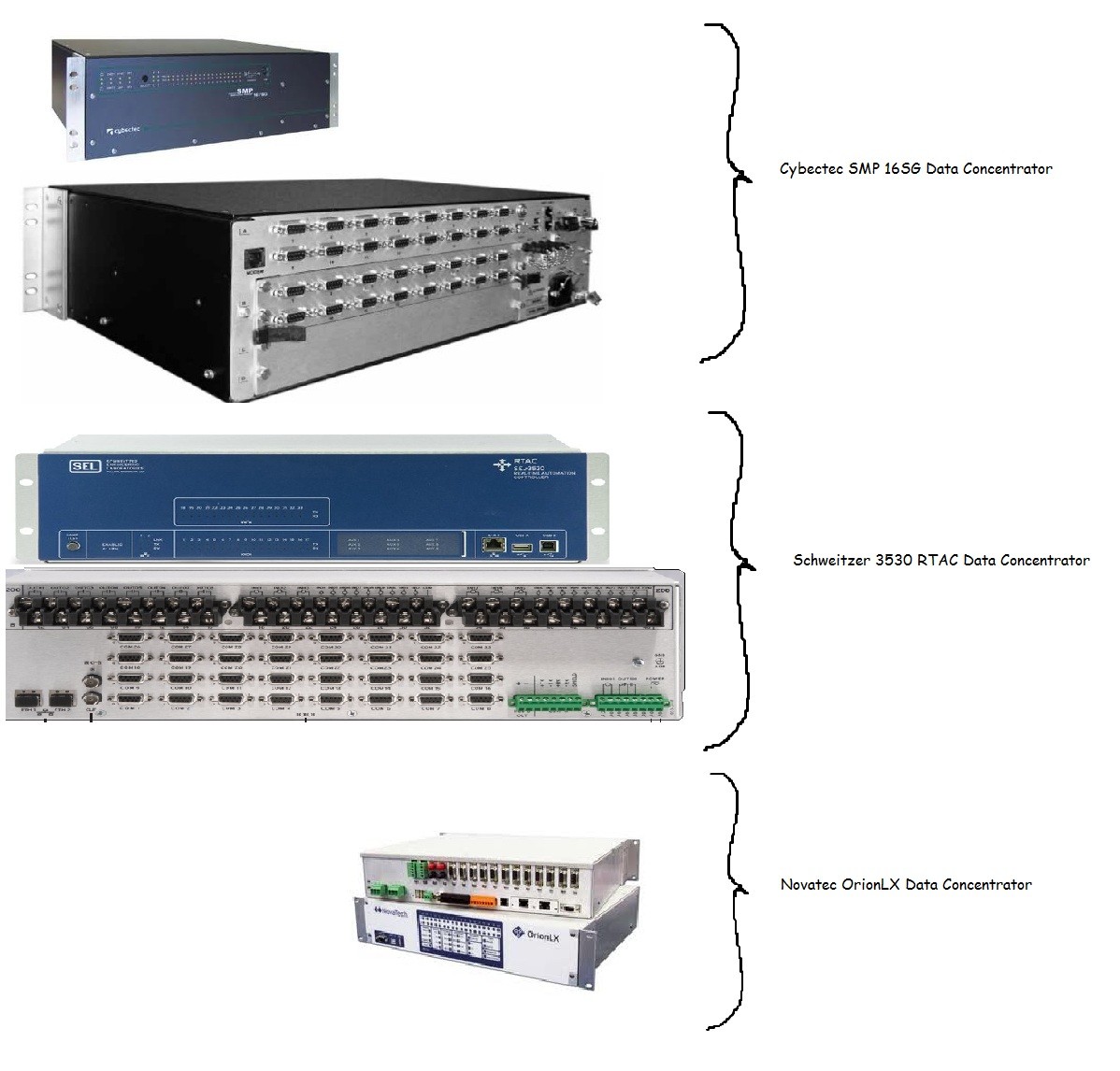
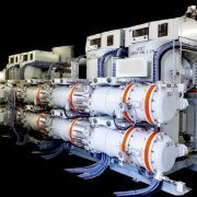
The Remote Terminal Unit (RTU) panel in a substation control house serves to implement the data acquisition part by concentrating the data. It utilizes a data concentrating device that has lots of I/O ports on it. When connected to all the IED’s (in a star topology typically), this device polls them to gather the data and transmits it to a remote master and/or client server stations. I/O ports on modern concentrators are not just limited to serial RS232 ports, they come fitted with ethernet ports such as fiber ports and RJ45 ports (for CAT5 cable). These ports enable Internet Protocol (IP) based station LAN or WAN networks. See picture 1 for some of the popular data concentrators in the power industry.
Let’s move on to IED communication now. IED’s like a microprocessor relay transmits information like alarms, equipment status (of equipment it is monitoring), trip information, etc. to the RTU via its communication port. Specifying the right communication cable is the first step in setting up the communication path. To make these two devices actually “talk”, however, you will need to make two things happen.
- Both the concentrator and the relay must speak the same language. Industry favorites are Modbus TCP/IP, Serial, and DNP3.0 with the latest being IEC 61850. In addition to these, some proprietary protocols like Mirrored Bits by Schweitzer can be used for communication provided only Schweitzer devices are used to build the network.
- Configure the concentrator to locate the relay in the substation network. Map all the digital points in the relay that need to be polled.
Each IED that generates data which needs to be collected, needs to have a unique address assigned to each one of its data points. The data concentrator will then poll these data points and transmit the data to a remote master. Big substations like those classified as bulk power substations can have as many as 20,000 or more data points. With ever growing functions offered by modern microprocessor based relays, it is easy to pile-up on more and more data points for monitoring or control. Fortunately, with drag and drop functionality and standard data point templates of many IED’s, a modern data concentrator makes mapping of thousands of data points less burdensome for engineers.
Legacy SCADA systems, which you will likely come across in some old substations, have the data points from various devices such as microprocessor relays, auxiliary relays, pilots relays, smoke detectors in the control room, etc. hardwired to the RTU’s digital status input boards. One advantage of this physical hardwiring is that it does not require mapping of the IED’s. However, as simple as it may seem, it is expensive to terminate every data point on the terminal blocks.
Supervisory Control
Among the available data points, only about 10% are utilized to implement some form of control function. To obtain this control input, data must be transmitted to a control center to elicit a supervisory response. This requires moving data on the WAN. However, supervisory functions can be implemented locally using the concentrators powerful logic functions. When necessary they can be used to analyze system events and provide circuit breaking (in control circuits), interposing relay, or latching relay functionality.
Data Concentrators as Gateway Devices
Data concentrating devices provide several additional capabilities. One of them is to serve as a gateway device. That is, any connection to a WAN system is made at only one point in the substation network and is made using this device alone. A gateway device does the following:
- It sets up a firewall, keeping intruders away.
- It provides a secure connection allowing secure data transmission adhering to NERC CIP requirements. Remote connection can be established via the internet using VPN, leased telephone lines (dial-up), wirelessly using a microwave tower, or via hardwired fiber.
- It supports a whole host of protocols and protocol conversion capability. This lets remote users to communicate with IED’s that not only “speak” legacy Modbus or serial but also the new DNP3.0/IEC 61850 protocol or a device specific proprietary protocol.
- It provides web based Human Machine Interface (HMI). Its built-in web server can serve one-lines of the substation to a remote user using a web browser. If HMI is required inside the control room, additional devices like a display monitor, keyboard, and mouse should be installed in the RTU panel.
Since real estate is premium inside a control room, replacing legacy SCADA systems with the new data concentrator enables you to do more with less (footprint).
To Network or Not To Network
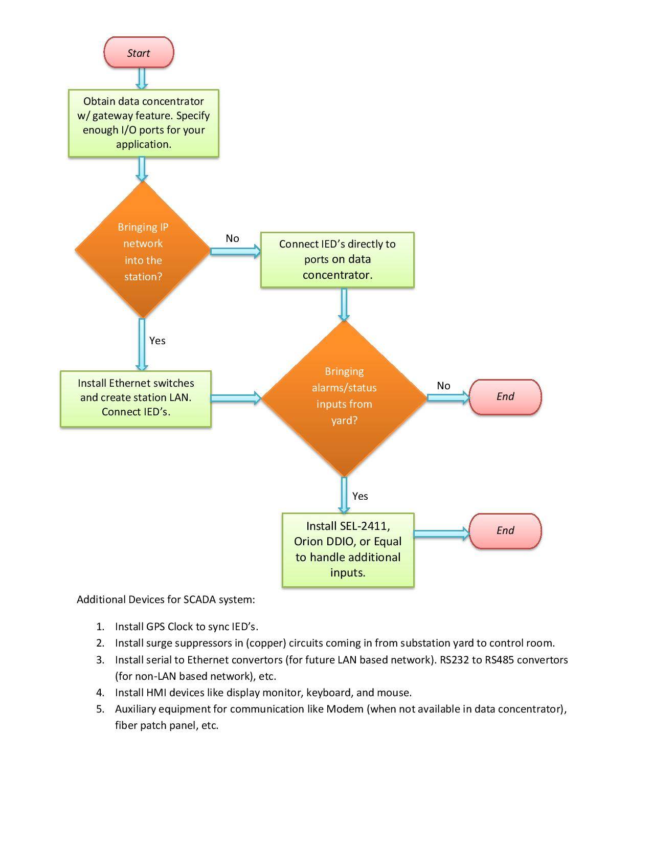
Creating a LAN using ethernet switches and putting all IED’s on this network makes the system susceptible to attacks. If this system controls a bulk power substation or some other critical asset then the network must be secured. Therefore, a virtual boundary around the network must be created such that any incoming request to access an IED inside the boundary, keeping in mind that the entry point is not just at the gateway device, must be verified. Maintaining an audit trail for both electronic and physical access may become necessary for such an asset. Therefore, creating a network is not just about bringing an IP network into the substation, it is just as important to secure it, both on WAN and LAN.
You can create a network without a station LAN. If the substation is small, you can connect all station IED’s directly to the data concentrator. No ethernet switches are required. Additional I/O ports on this device can be installed as necessary.
Design Guide for Setting Up Your Own SCADA System
* * * * *
References:


Pingback: Scada System For Substation Pdf? 17 Most Correct Answers
Very nicely explained.