These terms were coined over the years to identify the appropriate short circuit current magnitude that engineers could use to rate the switchgears, switchboards, panelboards, circuit breakers, fuses, etc.
But before I explain each term, let’s get some basics out of the way.
From circuit theory, at the point of short-circuit, the fault current is described by the following equation.
i(t) = \sqrt2 \frac{V}{Z}\sin(\omega t - \frac{\pi}{2}) + \sqrt2 \frac{V}{Z} e^\frac{t}{\frac{X}{2\pi fR}} Amps
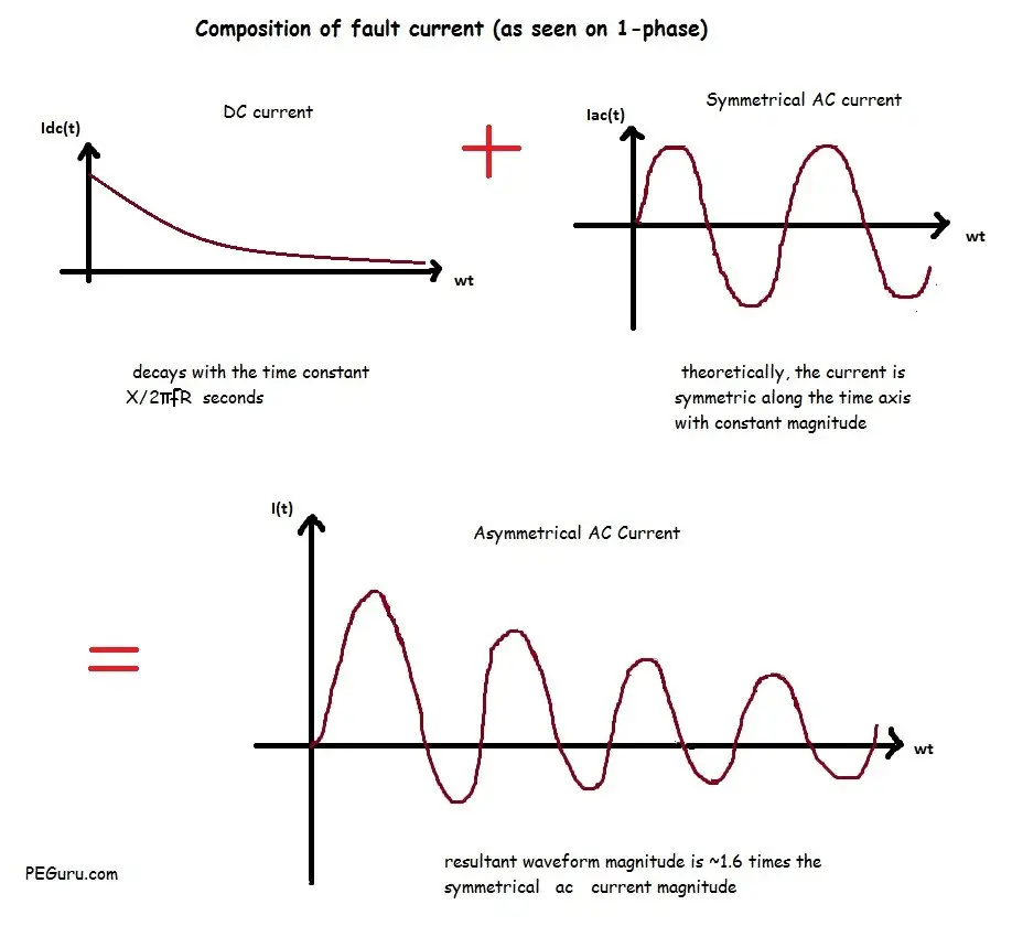
If you look closely, the fault magnitude is a combination of AC component (the Sine function) and DC component (the exponent e function). Both functions are plotted separately in Figure 1 below. Their combination yields the i(t) curve, also shown in the same figure.
Now, let’s look at each term and their context with respect to the fault curve.
Asymmetrical (RMS) Current
This term refers to fault current magnitude at ½ cycle point. At this point the curve is highly asymmetric around the x-axis.
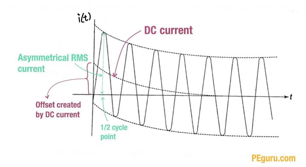
During the first half of a cycle, the fault current is at its largest magnitude – occurring at a moment when the voltage wave (not shown) is passing the reference axis.
The asymmetry is brought on by the DC offset (as shown in Figure 1). With this offset, the RMS value of the asymmetrical current is about ~1.6 times the symmetrical current.
A quick word on Root Mean Square (RMS) quantity: the RMS quantity of an AC signal (voltage or current) is a phantom quantity. It is created to compare the AC magnitude to that of the DC i.e. making sure you are comparing apples to apples. So, for example, a 5Amp RMS AC current is the same as a 5Amp DC current. However, the peak value of the AC quantity will be \sqrt2 \times 5 Amps = ~7 Amps.
Now that we know RMS magnitude is NOT the same as peak, in 1987 the IEEE committee established the term (peak asymmetrical) to make it clear that the peak asymmetrical current generates the most destructive force and not the RMS quantity. How destructive? Well, peak asymmetrical current is about ~2.7 times the symmetrical current.
To summarize, you have
- Symmetrical fault current (i.e. no DC offset)
- Asymmetrical (RMS) fault current = 1.6 \times symmetrical current magnitude
- Peak asymmetrical fault current = 2.7 \times symmetrical current magnitude
Momentary Rating
This is a half cycle rating and quite similar in meaning to RMS asymmetrical amps except it does not have the same unwieldy name.
It highlights the ability of equipment like switchgear, switchboard, circuit breaker, etc to withstand RMS asymmetrical amps.
Close & Latch Rating or Making Current
This term highlights the capability of a circuit breaker to close into a fault at the 1/2 cycle point and stay in that position without destroying its poles.
Interrupting Rating
This term pertains to fault magnitude between the 2nd cycle and the
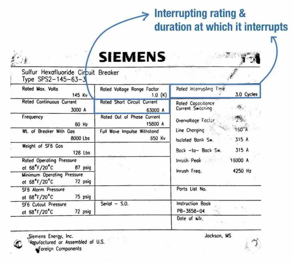
So, what is the significance of the interrupting rating? In medium voltage and high voltage systems, circuit breakers and fuses are capable of operating in 2 cycles to 5 cycles. Therefore, this term applies to these protective devices and their interrupting capability.
Here’s a picture of the circuit breaker nameplate with the interrupting rating listed. This breaker can interrupt a fault current of 63,000amps (or lower) at 3-cycle mark.
For switchgear, interrupting rating may also be specified as short circuit MVA. Why you may ask? The operating voltage of the power system fluctuates based on load. Also the fault current a device can interrupt is inversely proportional to the operating voltage. So regardless of what the operating voltage is, the product of (pre-fault) voltage and interrupting current rating is constant. It is logical to specify a SC MVA rating and not fret the voltage and current magnitudes.
Short circuit MVA is given by
MVA_{sc}=\sqrt3 \times V_{L-L} \times I_Lwhere,
V_{L-L} = Line to line voltage in kV
I_L = Interrupting current in kA
Symmetrical (RMS) Current
This term refers to fault current magnitude at the 8th cycle and beyond. In 8 or more cycles (typically 15), the fault current will decay to
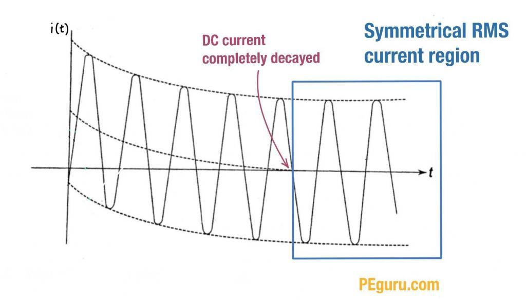
Slow operating devices (like molded case breakers) typically used in low voltage systems (1000V and below) use symmetrical RMS rating. The spec sheets implicitly list their ratings in symmetrical amps.
Low voltage panels too are rated by their symmetrical current rating.
The \frac{X}{R} ratio plays a significant role in how fast the DC current decays. In highly inductive circuits where \frac{X}{R} > 15, the DC current takes a while to decay. In other words, the equipment exposure to the asymmetry is prolonged.
Fault current rating is only one piece of information that defines a protective device. In this article you’ve learnt the various terms associated with the fault current magnitude.


Hi
RMS is not a phantom quantity. Just look at the remains of equipment that wasn’t designed to withstand the fault current and you’ll come away with a deep respect for RMS .Thus switches and transformers are designed to withstand this inrush of current based upon the calculations as found in establishing fault current for the AC system .
J. Jason Amodeo
Correct. RMS value of a current is the equivalent of a DC current that produces the same power. In other words, 127 Vac is a sine wave with 180V peak value and X current. The power it produces is equivalente to a 127V DC supply and X current.
How to convert / calculate from symmetry short circuit current to asymmetry short circuit current,
@Allan Camello, the difference is that interrupting current is the switch/breakers ability to interrupt the flow of current, whereas the momentary rating is the ability of the switch to remain intact and operational while experience a through fault current flow of “said” kA.
To illustrate: a load interrupting switch will have an interrupting rating of 600A, but a momentary “withstand” of 40kA. It will SWITCH 600A of current, but if the upstream breaker closes back into a fault, or clears a fault, it will withstand the momentary current flow of up to and including 40kA.
What is the difference between interrupting current and momentary current?
make and break current rating(IEC) is then associated synonymously with the close and latch current rating(ANSI).
Good information
i want to check asymmetrical waveform in my relay with current source, how it is possible
Got it.
we also use make current and peak current…