To understand how transformer winding connections are made, in this article I will build a three-phase transformer delta-delta (with 180degree phase-shift) using three (3) single-phase transformers. Although this exercise seems moot for substation design, practical applications of single-phase transformers exist. For instance, as a station-service source.
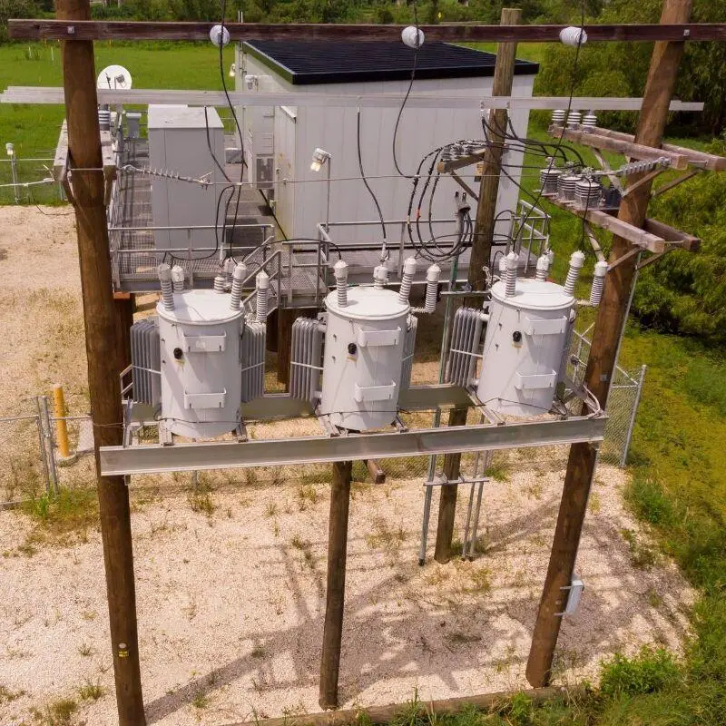
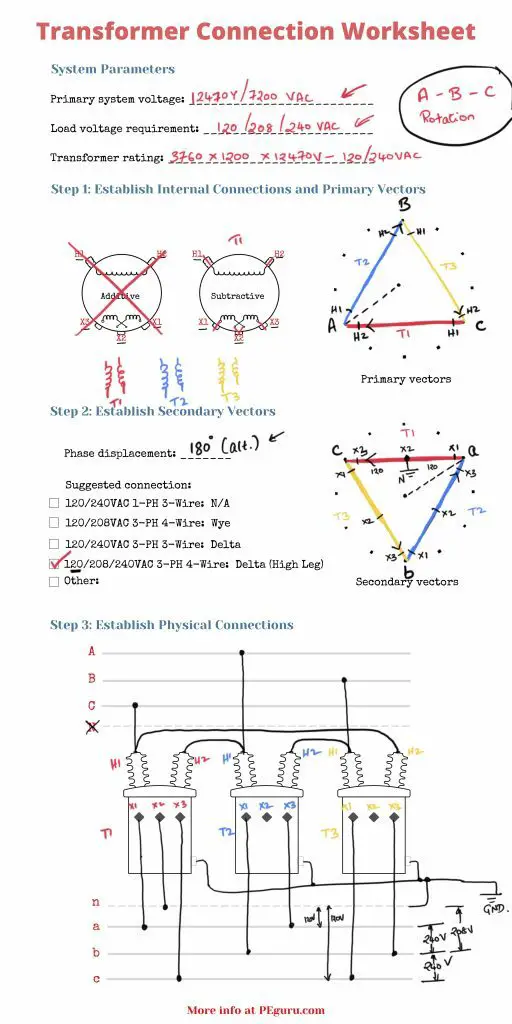
Also, to guide you step-by-step, I’ve prepared the below worksheet (free to download), used through-out this exercise.
Finally, before you begin the exercise, check the video below. Both the video and the article work together, filling all the blanks in the worksheet.
Step 1: Develop vectors for transformer HV windings
To figure out whether the primary windings get tied as a wye or a delta, you need to understand the primary voltage rating and the transformer coil voltage.
Primary system voltage rating
First, let’s look at the voltage rating and the number of wires of the source.
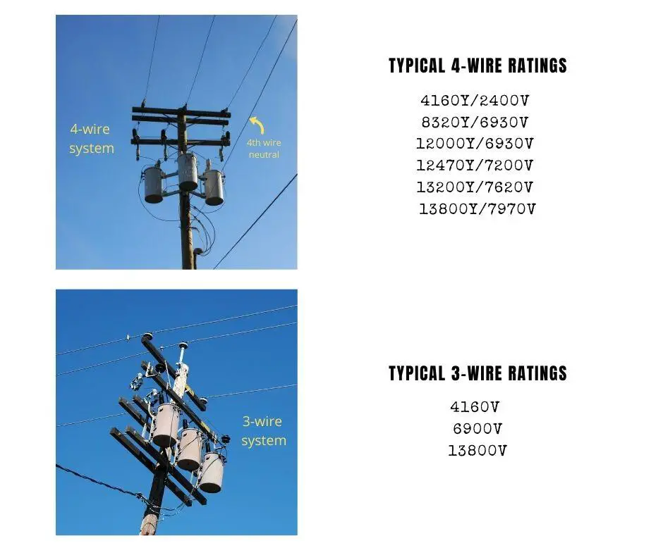
In 4-wire systems, you have two voltage ratings to pick from – either phase-to-phase (the higher number) or phase-to-ground. In 3-wire systems, there’s only one rating – phase-to-phase.
For this exercise, Let’s assume a 12,470Y/7200V 3-phase 4-wire AC system will feed the transformers.
Note: at medium voltages, the number of wires reveals whether you have a wye or a delta primary system (in other words it indicates how the secondary windings of the source transformer are wired.)
Transformer coil voltage
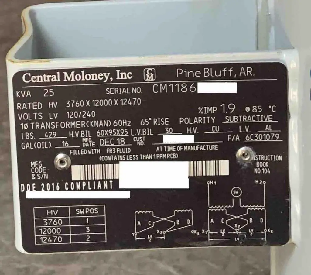
Two possible transformers that work with the above-established source rating are provided below.
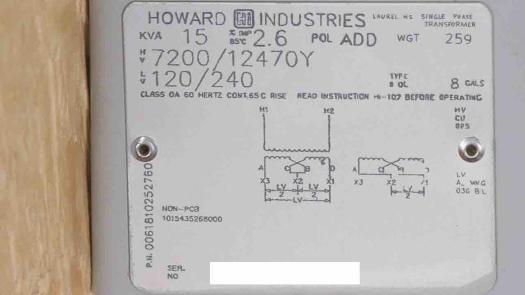
If you look at the nameplates, the HV voltage ratings are furnished differently.
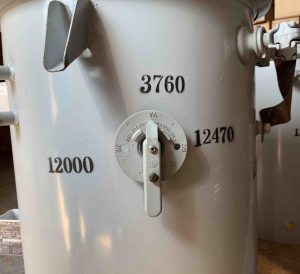
One is 3760X12000X12470V and the other is 7200/12470Y. So which rating can be applied across the H1-H2 terminals of the transformer?
Rule of thumb:
When you see the ‘/’ oblique sign, the lower number represents the coil voltage. You can only apply the lower number to the H1-H2 terminals. Under no circumstance can you apply the higher voltage. With respect to transformer #2, do not apply 12470V across H1-H2 of this transformer.
When you see the ‘X’ cross sign, you can apply any one of the voltages listed. With respect to transformer #1, you can apply either 3760, 12000, or 12470 to the H1-H2 terminals. Just make sure you choose that tap using the lever that’s provided.
To further understand the implications of the coil voltage, see the below video.
Let’s pick quantity three of transformer no.1 for our exercise.
Picking vector type for HV windings
Since we assumed a 12470Y/7200V 3-phase 4-wire system, there’s only one way to connect the H1-H2 terminals of our 3 single-phase transformers – a delta.
With a delta connection, you are applying full phase-to-phase voltage, which is OK since you can set the lever at 12470V setting (see image above).
If you tie them as a Wye then you are only applying 7200V to the H1-H2 terminals of each transformer. This will not develop the correct voltage at the LV winding because there is no 7200 setting on the HV winding- only 12000 and 3760.
Additional detail: Identify transformer polarity
Per NEMA standards, any transformer with a 167kVA (and lower) power rating and 9000V (and lower) coil voltage rating is manufactured with an additive polarity. Transformers high in any one rating ends up subtractive. This affects the physical location of X1-X3 terminals.
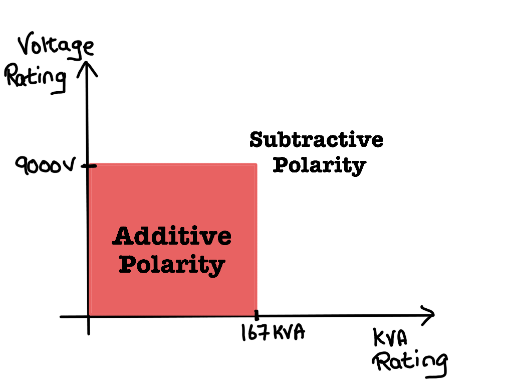
Because we chose a 25kVA 3760X12000X12470V -120/240V rated transformer, it is built subtractive.
Step 2: Develop vectors for transformer LV windings
To figure out whether the secondary windings get tied as a wye or a delta, you need to understand the load voltage requirement.
Load voltage requirement
Auxiliary AC loads in substations (like motor loads, heating loads, lighting loads) are typically 120V 1-phase, 208V 1-phase or 3-phase, or 240VAC 1-phase or 3-phase.
For this exercise, let’s assume we have all three types of loads: 120 (1-phase) / 208 (1-phase) / 240VAC (3-phase).
Note: at load-end, the number of wires does not reveal whether you have a wye or delta secondary. In fact, you can supply a 4-wire delta (you’ll see more of this here) or a 3-wire wye. The only fact that reveals how the LV winding is wired is the winding ratio, is it 120/208 (i.e. 1:1.732), or 120/240 (i.e. 1:2), etc. The 1:1.732 ratio requires a wye while the 1:2 ratio, a delta.
Determine which LV terminals (X1-X2-X3) get used
On the LV side, we need the full 240vac rating, to supply our 240vac load. To obtain this, the LV windings get tied in series.
Now, let’s derive the 208vac service. There are two ways to go about this.
In one way, you must tie the LV windings of a transformer (a.k.a. tub) in parallel. This gets you 120vac only from the one tub. Now tie 3 tubs in a wye, and you get 208vac between phases. See the middle image below. With the wye connection, you get a 3-phase 208vac service. But because the windings are paralleled, you lose the 240vac.
Alternatively, if you keep the 240vac full LV winding, you can still get the 208vac service. Only this time, you will only obtain a single-phase 208vac service. Just ground the center terminal of only one tub and tie all three tubs as a delta. See the last image below.
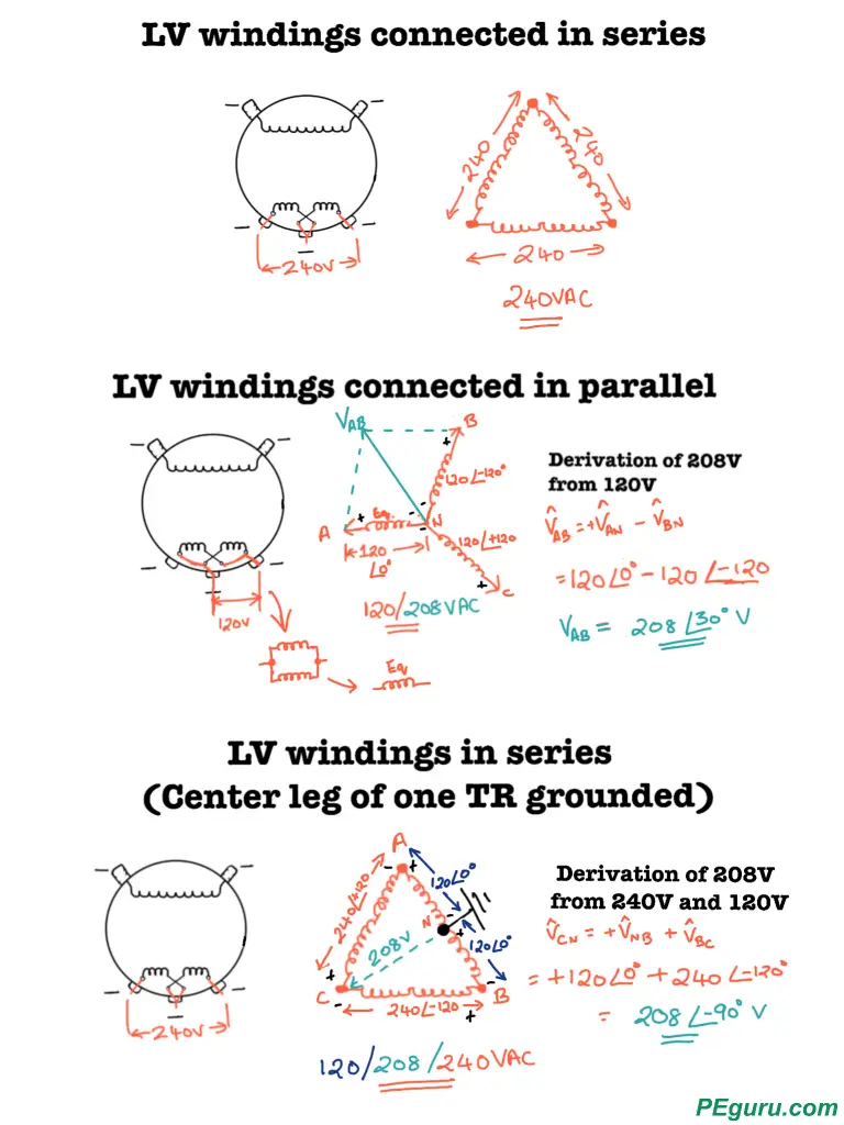
For our example, we tie the LV windings as a delta, and because we need 120/208/240 service, we use all three terminals X1-X2-X3 on the one tub and X1-X3 on the remaining two tubs.
Phase displacement (between HV and LV vectors) and direction of phasor rotation
Now that we know what the LV winding vector is, it’s time to rotate it -clockwise (making high-side vectors lead the low-side). If there are existing transformers at the substation and you are paralleling this new bank, then match the phase displacement. Otherwise, pick one. The standard would be to pick the least possible displacement. This would be zero degrees in a wye-wye/delta-delta setup or 30degrees in a delta-wye/wye-delta setup.
Now would also be the time to write down the phases. Write down A-B-C clockwise around the primary and secondary vectors (assuming an A-B-C rotation system). Transformer designation T1, T2, and, T3 follows the same clockwise pattern.
Correlating HV and LV vectors
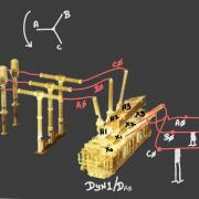
HV and LV windings of the same (single-phase) transformer are wound on the same core. As such, the associated HV vector and LV vector are parallel to each other. We apply this concept to establish LV vectors. Make sure to watch the video (at the beginning of this article), where I draw this out. You can also see the image below where I drew the final setup. Did you observe the HV and LV vectors of T1, T2, & T3? Aren’t they parallel? As should be the case (of windings on the same core).
Step 3: Determine polarities and mark transformer terminal numbers on the vectors
With the primary and secondary vectors drawn, the following finishing touches help with final transformer winding connections.
- With Delta-Wye or Wye-Wye setup where the LV vectors are a Wye. Start establishing the polarity direction with the LV vectors and then proceed to mark the HV vectors.
- Combine all X2’s and ground them.
- X1’s tie to the phases.
- Match polarity directions on the HV vectors.
- With Delta-Delta, you can establish polarity directions on any winding. Ideally, you set it up such that H1-H2’s connect sequentially, as shown below.
I highly recommend you watch the video to make sense of this step.
Here’s how the final connections look for our transformers.
Error traps
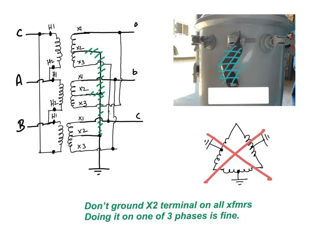
Watch out how you connect X2 terminal on a delta high leg setup
Do not tie all X2’s to the ground as shown in the image below. I’ve done it once and it blew the high side fuses. The theory is by tying all X2’s to ground, you are reducing the counter magnetomotive force (MMF) that’s developed in the core (Lenz’s law). The induced current (in the core) ends up being more in-phase with the voltage, leading to a short-circuit.
Re-landing different phases after establishing vectors
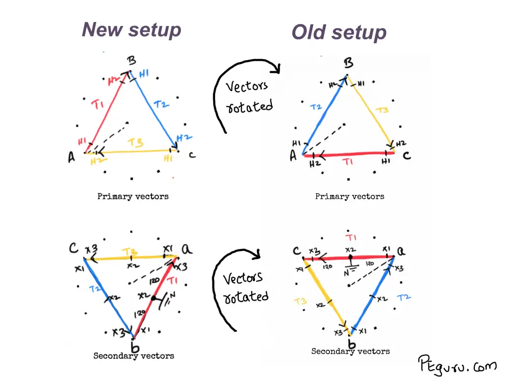
Notice how, in this exercise, we ended with C-phase on the H1 terminal of the transformer T1. Would you like A-phase on H1? The fix is simple. Keep the A-B-C and a-b-c text fixed and rotate all vectors (HV & LV) simultaneously until the H1 of T1 meets the letter A. The final vector config would look like below.
More transformer winding connection exercises
Use the blank worksheet provided, create your 3-phase vectors, and transformer winding connection for the following scenarios.
- Primary system: 4160V 3-phase 4-wire; Load requirement: 120/208V 3-phase 4-wire, Transformer rating: 2400/4160Y – 120/240V 25kVA, Phase displacement: 0deg (standard)
- Primary system: 7970/13800V 3-phase 4-wire; Load requirement: 120/208V 3-phase 4-wire, Transformer rating: 7970/13800Y – 120/240V 50kVA, Phase displacement: 210deg (alternate)

It really interests me to read such articles, thanks for sharing. Blogs like yours and https://tsca.com.ph really helps me learn more day by day.