Power transformers increase or decrease voltage and current magnitude in a power system. This transformation occurs because of Faraday’s induction principle and the variation in ampere-turns (or winding turns). Do note, the power transferred remains the same (minus few core and copper losses).
Transformer Design
A power transformer contains 6 key components.
- Core
- Winding
- Bushings
- Load tap changer
- Tank
- Cooling
As a power engineer, understanding the component design means you can specify transformers correctly.
Core design
What’s the purpose of the transformer core?
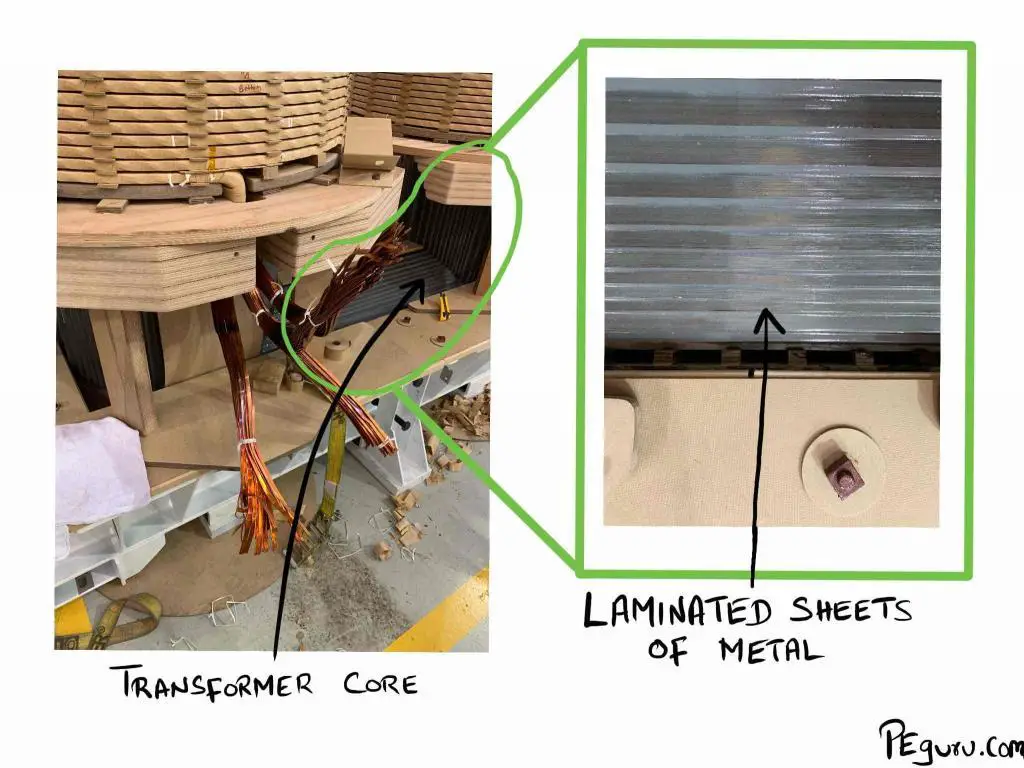
The core serves as a middleman. Because the primary and secondary windings are electrically isolated, the core supports the induction process by providing a path for the magnetic flux to move from the primary winding to the secondary. To support this mission, it must perform two things right
– Provide good magnetic permeability.
– Minimize flux leakage.
This is accomplished utilizing laminated sheets of Cold Rolled Grain Oriented (CRGO) steel.
What’s the difference between core-type and shell-type transformer?
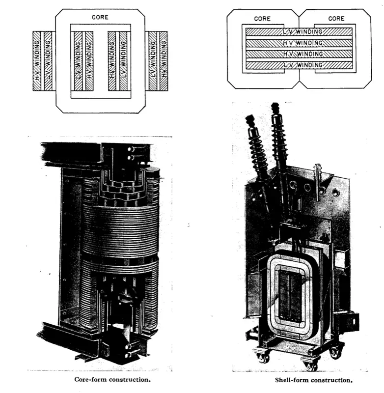
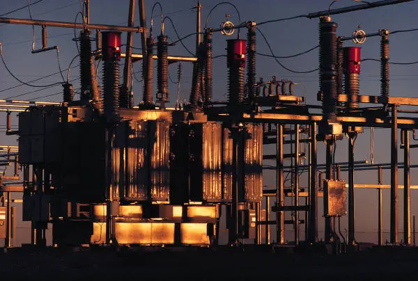
The laminated sheets are formed into either a core type or shell type. Observe their differences in the images below.
Why is the shell-type transformer better than the core-type transformer?
The shell-type transformer, although expensive to make (because of additional material) is better than the core type for the following reasons
1. Provides high short-circuit current withstand capabilities. Essentially, the laminated sheets of metal around the windings brace it when they flex or twist during short-circuit.
2. The outside limbs provide extra path for the leakage flux to flow. Without this escape route, like in core-type, local overheating occurs.
3. It can withstand a voltage surge better because of interleaved disc windings (explained below).
Winding design
How are the transformer windings designed?
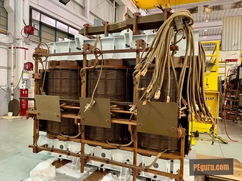
The windings conduct current. As such, you can increase the voltage induced by increasing the turns around the core and decrease the voltage by decreasing the turns.
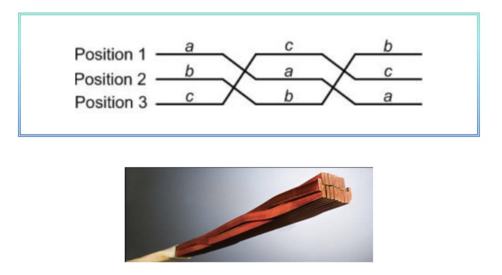
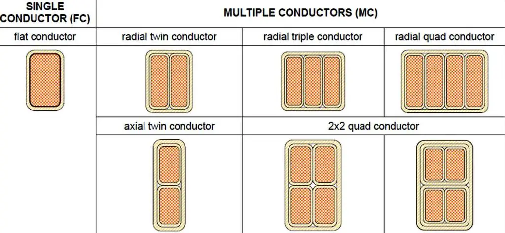
For primary and secondary windings, employing a continuously transposed conductor (CTC) provides high mechanical stability (because of the way magnetic fields cancel). For tertiary or stabilizing windings, the flat copper conductor gets used.
How does interleaving the transformer windings help?
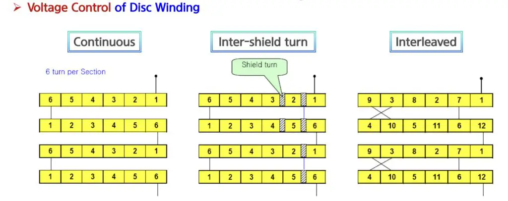
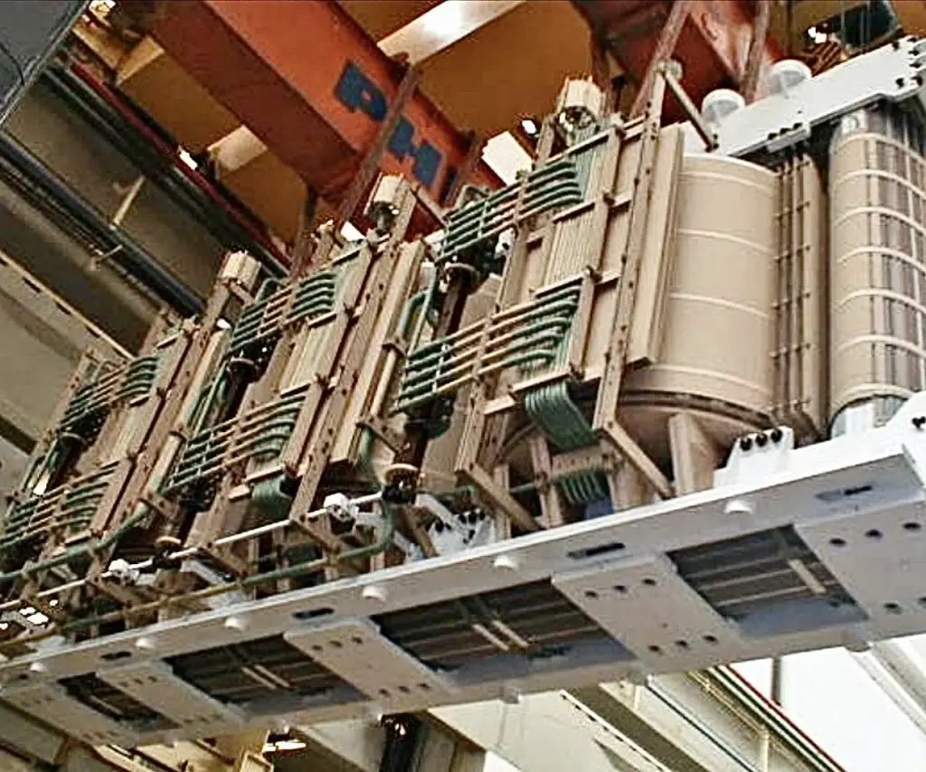
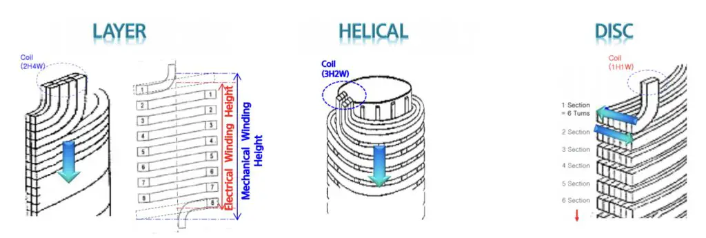
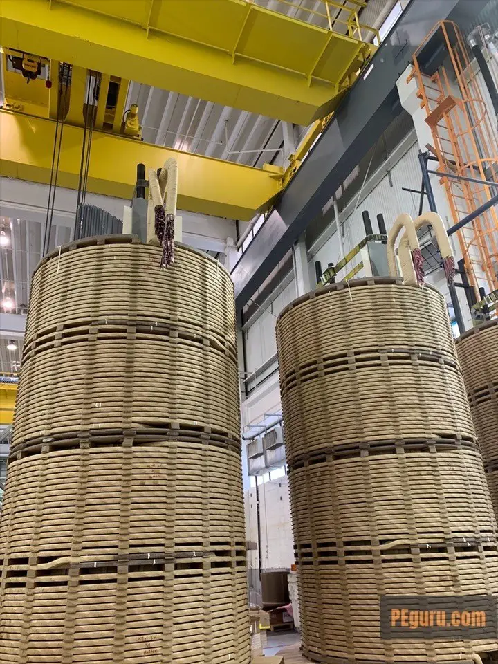
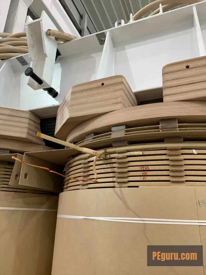
Although windings can be simply spun helically around the core, interleaving the turns (see image) creates mini-capacitors that helps break down the incoming voltage surge and bury it into the windings. Inserting a shield wire (flat copper) between turns is another method of channeling the surge.
How is insulation applied to the transformer windings?
To channel the current, every inch of copper is (kraft) paper insulated: turn-to-turn, between LV winding and core, between HV and LV winding, between HV winding and core.
Bushing design
What’s the purpose of a bushing on the transformer?
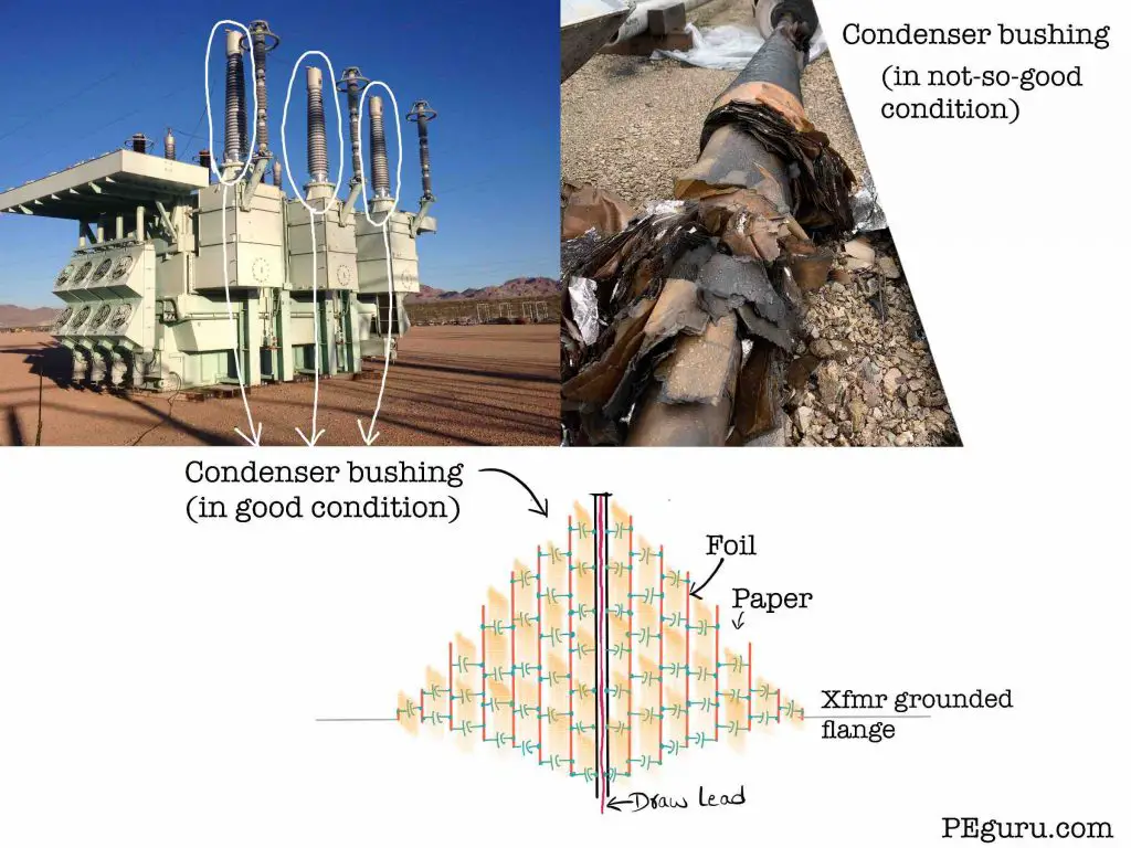
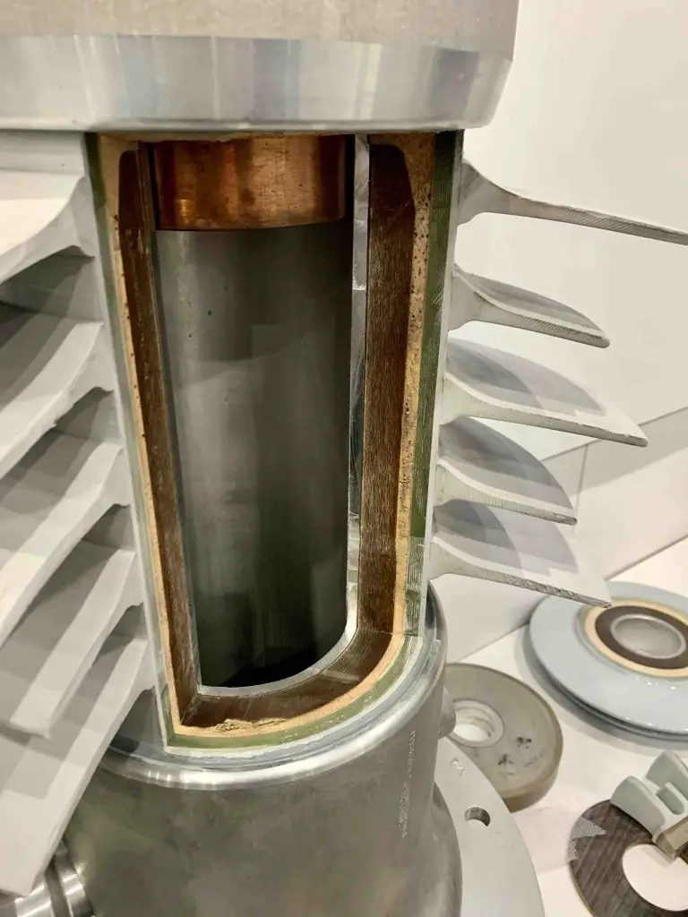
Bushings provide a path for the current to flow from the energized (high voltage) conductor to the windings inside the tank (without energizing the tank). You should be concerned with two points of contact. One, at the top, where the conductor lands. The porcelain insulator maintains the phase-to-ground clearance. Second, inside the bushing, the mini-capacitors created by paper and foil maintains the clearance (capacitors break down the voltage). This type of bushing is called the capacitance or condenser bushing. This is typical for transformers at HV, EHV, & UHV voltages. At medium voltages and below resin (dry) bushings are an alternative.
Load tap changer design
What’s the purpose of an On Load Tap Changer?
As the load increases or decreases, the voltage at the substation either decreases or increases respectively. To keep the voltage stable, the number of winding turns can be added or removed (remember, adding secondary turns increases voltage or vice-versa). This is the function of an on-load tap changer – stabilize the voltage by varying turns. The OLTC windings remain in the main tank (around the core) while the operator and its accessories mount in a separate compartment.
What does the load tap changer contain?
There’s hundreds-of-volts of potential difference between each tap inside the transformer. So, when you make or break a tap connection, the arcing is handled by the vacuum switches. When you bridge two tap positions, the potential difference drives the circulating current. The preventative autotransformer acts as an inductor, limiting the in-rush associated with the circulating current. This is your reactive type OLTC. Another variation is the resistive OLTC.
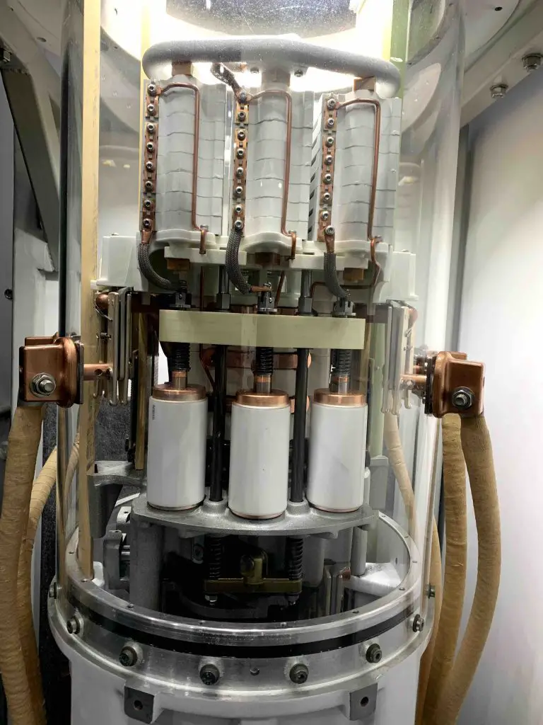
Vacuum switches (white bottles) on the LTC 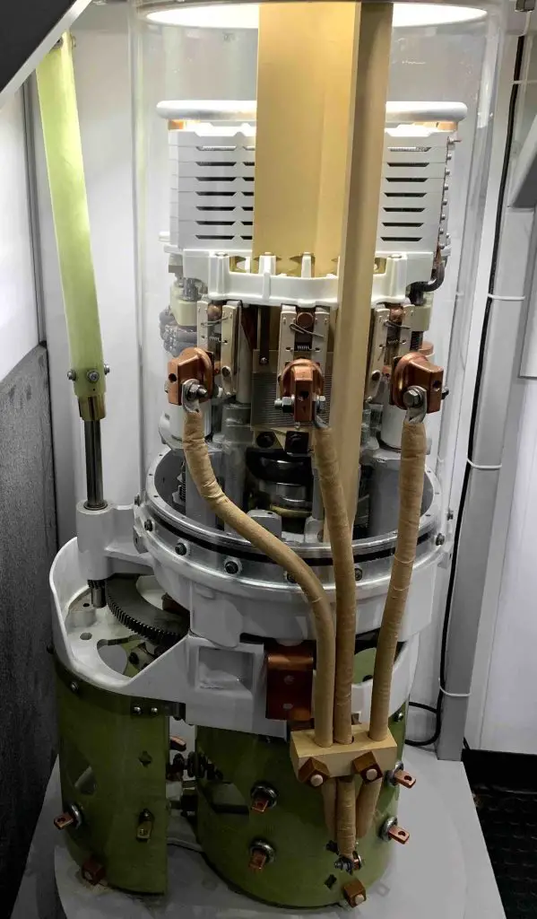
Tap changing mechanism 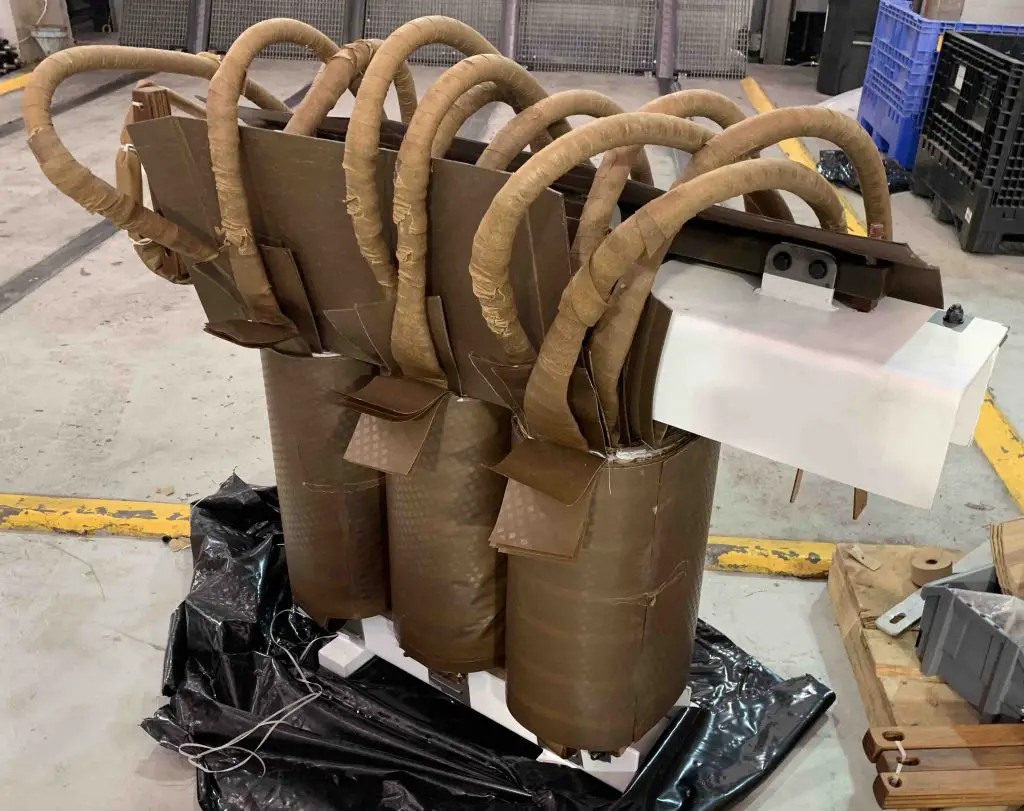
Preventative autotransformer regulates the in-rush current when bridging two tap positions
Tank design
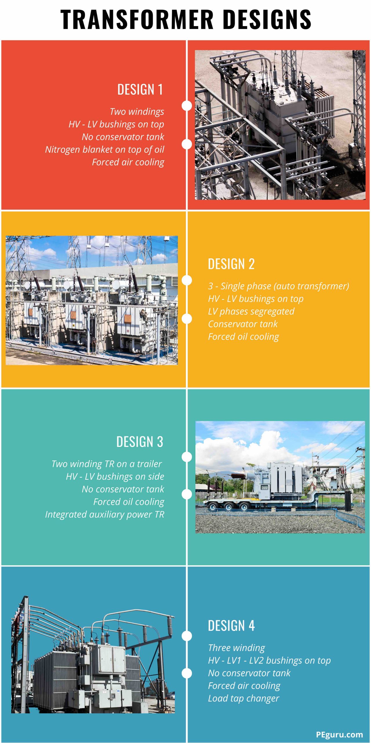
Tank design is where you get creative, to support location and project requirements. You can specify bushings on any side, install cooling systems, reduce sound using a unique tank panel, choose isolated phase bus ducts – segregated or non-segregated bus ducts, etc.
Another critical design decision is to pick a three 1-phase or one 3-phase transformer. Generator step-up transformers at large power stations, transformers at EHV substations go the three 1-phase route.
Three 1-phase transformers have each bank isolated from the other and thereby offer continuity of service when one bank fails. A single 3-phase transformer, whether core or shell type, will not operate even with one bank out of service. This 3-phase transformer, however, is cheaper to manufacture, has a smaller footprint, and operates relatively with higher efficiency.
Cooling system design
How is heat managed inside the tank?
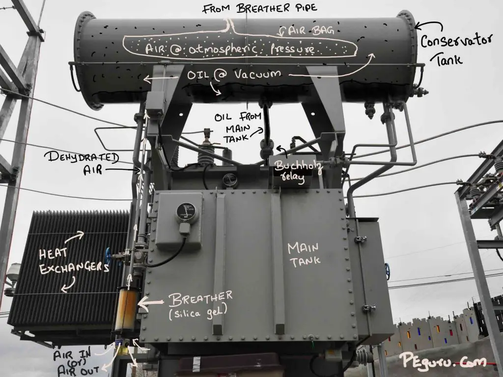
The current flow in copper winding generates heat. The eddy current & exciting current in the core generates heat. The mineral oil extracts this heat. Normally, the natural convection flow of oil removes heat: hot oil rises to the top -> moves to radiators -> oil cools, settles down, and moves to the main tank -> oil heats up again and rises (process repeats).
To improve cooling, attach a bank of fans to the radiators or heat-exchangers. To further improve, force the oil movement (through tank or windings) using pumps.
Because the oil can pickup moisture/oxygen/debris, oil preservation or filtration system helps prolong a transformer’s life.
What’s the purpose of a conservator tank?
Oil expands and contracts with transformer loading. Because the tank is sealed and under vacuum, the oil volume is controlled by two methods.
Method 1: Use a conservator tank. The main tank gets completely filled. The excess oil spills into this tank.
Method 2: The main tank is not completely filled (but core and windings are submerged). A “blanket” of nitrogen gas fills up the void at the top. As oil expands, the gas is released. As it contracts, an external nitrogen bottle refills the gas.
Can the transformer operate beyond its nameplate rating?
The transformers power capability is limited by the thermal rating. This means the transformer can be operated beyond its MVA rating as long as the temperature of its top oil stays within the 65ºC temperature rise above ambient temperature (See IEEE C57.12.00-2015 standard). For instance, if the ambient temperature is 45ºC then the transformer can be pushed to a value less than 45ºC + 65ºC = 110ºC.
Prolonged overloading of the transformer is not recommended on account of saturating its core (higher losses), loss of life expectancy, and deterioration of winding insulation.
Transformer Winding Connection
Once the coils are in place, the three primary windings and three secondary windings can be tied either as a delta or a wye (or star). One such setup is shown below.
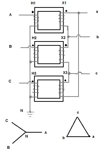
Although it may seem you are short-circuiting by tying one end of the coil to neutral-ground (in a star) and by tying one coil to another (in a delta), this is not the case. These connections work because of Lenz’s law.
The use of any one combination: delta-star, star-delta, star-star, or delta-delta makes a huge impact on the design of the power system. So the choice of connection is critical.
Wye-ground Wye-ground transformer advantages
- Provides insulation savings, leading to cost savings on the transformer.
- Simplified phasing i.e. no phase shift occurs – simplifies transformer paralleling.
Wye-ground Wye-ground transformer disadvantages
- Harmonics (unwanted frequencies) propagate through the transformer, potentially causing radio interference.
- The zero sequence current flows through the transformer.
- External line-to-ground faults will trip the transformer (if neutral connection allows fault current back-in, then in a differential protection zone, the current entering is not the same as current leaving).
- There’s a possibility to load the phases differently leading to an unbalanced high voltage system.
Delta Wye-ground transformer advantages
- Because the delta winding traps zero sequence current, the upstream relay on the delta-wye transformer can be assumed to pick up for only high-side ground faults. This allows for very sensitive pick-up settings. In contrast, the wye-wye combination allows zero-sequence current through – making it difficult to assess the location of the fault. In short, relay protection is improved.
Delta Wye-ground transformer disadvantages
- Because of the phase shift associated with these transformers, closer attention needs to be paid to the design. Potential error traps occur during paralleling and CT wiring.
- High insulation cost leading to an expensive transformer.
Additional details on the pros and cons of various winding configurations can be found in General Electric’s paper titled The Whys of the Wyes.
To capture the pros of each combination, a power transformer can be fabricated with three sets of winding (instead of just two), typically primary-wye, secondary-wye, and tertiary-delta.
Delta Tertiary and Its Application
In a three winding wye-wye-delta transformer, the delta tertiary winding allows for connecting a:
- Capacitor bank – for voltage or power factor correction
- Reactors – to prevent voltage from bulging (Ferranti effect) on EHV lines during lightly loaded conditions.
- Station service transformer – AC power for equipment inside the substation
- From the protection and control standpoint, it traps zero-sequence (ground fault) current. If you insert a CT in this tertiary winding, you can measure this current. Because this winding also traps 3rd harmonics, it is called a stabilizing winding.
- Delta tertiaries induce a current in one direction only, regardless of where the fault occurs – high side or low side. Thus, a directional relay can be polarized using the delta tertiary CT’s.
How Transformer Grounding Affects Power System Design
Without going into a lot of detail, for cost savings and safety, the star connection is the preferred connection for high voltage transmission. In this scenario, the common point – the neutral, is grounded or earthed. Doing this causes the phase to neutral voltage or phase to earth voltage to be reduced by a factor of 1/sqrt(3). You will not get this reduction with a delta (ungrounded) connection.
It only makes sense to use a delta-star transformer near the generating station where the delta is connected to the generator terminals and the star is connected to the high voltage transmission lines. With grounded star connection on the high voltage side, the transformer winding can be insulated for lower (phase-to-ground) voltages. The transmission system too will have a lower insulation requirement. These provide tremendous cost savings in the design and construction of the transmission system.
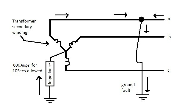
There is, however, a disadvantage in grounding the transformer neutral. When one line or all three lines on the star side short-circuits to the ground, the grounded neutral of the transformer serves as a return path for the fault current. These fault currents, when not cleared in fractions of a second, can severely damage the transformer and all the equipment connected to it. The ground fault currents are also rich in third harmonic currents. The third harmonics on the transmission line disrupts all communication channels (for instance, power line carrier – pilot relaying) in the vicinity.
But all is not lost with the star-delta/delta-star combination (because of neutral grounding). The delta connection offers high impedance to third harmonics and traps the ground fault current, thereby preventing it from propagating one side to another.
Summary
- Delta-star transformers: Applied at generating stations and load centers.
- Star-star-delta transformers: Applied at transmission substations (765kV, 500kV, 345kV).
- Grounding the neutral provides higher ground fault currents however the cost savings realized by lower insulation requirements makes neutral grounding acceptable.


hello
would you please guide me how REACTOR RESISTANCE protect tertiary winding of power transformer against third harmonic density in 3 winding power transformer.
thanks a lot
Haris,
Low-magnitude turn-to-turn faults are usually detected by the sudden pressure relays (SPR) inside the transformer tank. They are more sensitive than a transformer differential protection scheme.
On an autotransformer, a SPR can mis-operate for close-in faults. Therefore, they are usually backed-up by some form of overcurrent protection. Now, phase-to-phase faults are unbalanced faults. Negative sequence elements can be set more sensitively without affecting load capability. For more info, see my article on Negative sequence protection: https://peguru.com/2011/08/enhance-your-power-system-protection-with-negative-sequence-relaying/
i am confused between connections of transformer windings and transformer connections with the main supply. can you please tell me that the delta-star, delta-zigzag, delta-delta are connections of transformer windings or the star transformer connection with the main in delta configuration?
why we use neutral or star connetion at secondary side of POWER TRANSFORMER while at 33/11kv substation 3 phase incoming and 3 phase outgoings are required?
Hello there. Can you explain a little bit about “sensitive turn to turn fault protection for power transformer” with a negative sequence.
Required information, can a power transformer winding connections changes does not impect on its working. We intend to change the connections of a power transformer from YDN to DYN i.e. primarry side star connection to be changed to delta and secondary side to be changed from delta to star + neutral earthing. (our primary voltages are 11,000volts and secondary 400volts.
In three winding transformer with stat-stat-deltal vector group, In delta side reactor is provided but reactor ground is not earther (Earth floating). Now, what is difference between grounded reactor and un grounded reactor. Please explain and what are factors influence?
Lola,
Lately, all CT’s are wye connected on either side of the transformer bushing. This is because the modern microprocessor relays can compensate for the phase shift using their logic. However, when presented with old electromechanical relays, the CTs on delta side of xfmr should be wye connected while the CTs on wye side should be delta connected. This is an interesting topic. I will work on writing an article on this in future.
In most scenarios, I have seen CTs on breakers (on either side of the transformer) provide the differential function. The only CTs I see on a transformer are located in the neutral winding.
How to connect CT on each connection of a transformer? Use diagrams please.
Chandan,
Breaker and a half scheme: When continuity of power supply is critical, you need to have a bus configuration that is flexible enough to reroute the power when feed from one side is down. Breaker and a half, provides this flexibility. Each bay has three breakers with two line tapped from a location between the breakers. The center breaker serves both the lines, hence breaker and a half. Ofcourse, this elaborate system is expensive.