Let’s understand the concept of per unit system by solving an example. In the one-line diagram below, the impedance of various components in a power system, typically derived from their nameplates, are presented. The task now is to normalize these values using a common base.
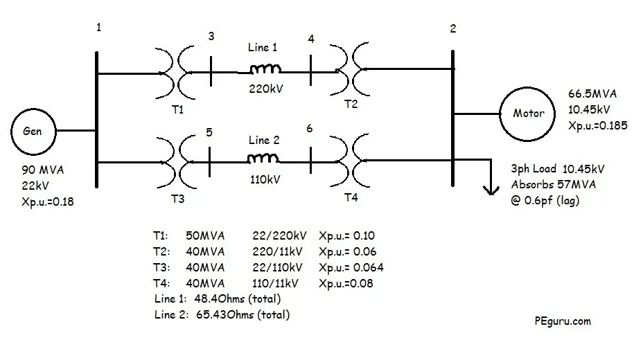
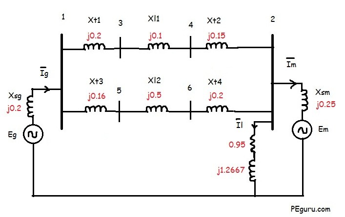
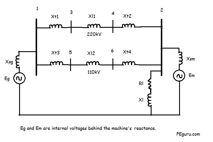
Now that you have carefully examined the system and its parameters, the equivalent impedance diagram for the above system would look something like the following.
Resistive impedance for most components have been ignored. Rotating machines have been replaced with a voltage source behind their internal reactance. Capacitive effects between lines and to ground are ignored as well.
To obtain the new normalized per unit impedances, first we need to figure out the base values (Sbase, Vbase, Zbase) in the power system. Following steps will lead you through the process.
Step 1: Assume a system base
Assume a system wide S_{base} of 100MVA. This is a random assumption and chosen to make calculations easy when calculating the per unit impedances.
So, S_{base} = 100MVA
Step 2: Identify the voltage base
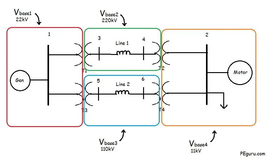
Voltage base in the system is determined by the transformer. For example, with a 22/220kV voltage rating of T1 transformer, the V_{base} on the primary side of T1 is 22kV while the secondary side is 220kV. It does not matter what the voltage rating of the other components are that are encompassed by the V_{base} zone.
See figure below for the voltage bases in the system.
Step 3: Calculate the base impedance
The base impedance is calculated using the following formula:
Z_{base}=\frac{{kV_{base}}^2}{S_{base MVA}} Ohms…..(1)
For T-Line 1: Z_{base}=\frac{(220)^2}{100}= 484 Ohms
For T-Line 2: Z_{base}=\frac{(110)^2}{100}= 121 Ohms
For 3-phase load: Z_{base}=\frac{(11)^2}{100}= 1.21 Ohms
Step 4: Calculate the per unit impedance
The per unit impedance is calculated using the following formulas:
Z_{p.u.}=\frac{Z_{actual}}{Z_{base}} …..(2)
Z_{p.u._{new}}=Z_{p.u._{old}}(\frac{S_{base_{new}}}{S_{base_{old}}})(\frac{V_{base_{old}}}{V_{base_{new}}})^2 …..(3)
The voltage ratio in equation (3) is not equivalent to the transformers voltage ratio. It is the ratio of the transformer’s voltage rating on the primary or secondary side to the system nominal voltage on the same side.
For T-line 1 using equation (2): X_{l1_{p.u.}}=\frac{48.4}{484}= 0.1 pu
For T-line 2 using equation (2): X_{l2_{p.u.}}=\frac{65.43}{121}= 0.5 pu
For 3-Phase load:
Power Factor: \cos^{-1}(0.6)=\angle{53.13}
Thus, S_{3\phi}(load)=57\angle{53.13}
Z_{act}=\frac{(V_{rated})^2}{\overline{S}^*}= \frac{10.45^2}{57\angle{-53.13}}= 1.1495+j1.53267 Ohms
Per unit impedance of 3-phase load using equation (2)= \frac{1.1495+j1.5326}{1.21} = 0.95+j1.2667 pu
For generator, the new per unit reactance using equation (3)
X_{sg}= 0.18(\frac{100}{90})(\frac{22}{22})^2= 0.2 pu
For transformer T1: X_{t1}= 0.1(\frac{100}{50})(\frac{22}{22})^2 = 0.2 pu
For transformer T2: X_{t2}= 0.06(\frac{100}{40})(\frac{220}{220})^2 = 0.15 pu
For transformer T3: X_{t3}= 0.064(\frac{100}{40})(\frac{22}{22})^2 = 0.16 pu
For transformer T4: X_{t4}= 0.08(\frac{100}{40})(\frac{110}{110})^2 = 0.2 pu
For Motor, X_{sm}= 0.185(\frac{100}{66.5})(\frac{10.45}{11})^2 = 0.25 pu
Per Unit System Ebook
If you think you learned something today then you will love the eBook I prepared for you. It has 10 additional and unique per unit problems. Go ahead, preview it on the right. Get the complete version for only $1.00. Thanks for supporting this blog.
Per Unit Systems: Ten Total Problems Solved With Detailed Explanation Aleen Mohammed
- Per unit systems is an important concept in power system analysis. So much so, it shows up in all exams pertaining to power. Besides being taught in higher education, it is quite commonly used by engineers in the power industry. Equipment impedances are furnished in per unit. Source impedance for fault analysis is furnished in per unit. In this book, you will find enough problems solved for you to get the hang of this subject.
To view full load amps due to motor load and inductive load at Bus 2, see this post.
Summary
- Assume a Sbase for the entire system.
- The Vbase is defined by the transformer and any off-nominal tap setting it may have.
- Zbase is derived from the Sbase and Vbase.
- The new per unit impedance is obtained by converting the old per unit impedance on old base values to new ones. See equations (2) and (3).



Can someone tell me what would happen if for T2 and T4, the Primary and Secondary were swapped i.e. T2 would be 11/220 and T4 would be11/110?
I have a simialr problem and I am getting two different values for Vbase4.
IJAJ :what do you mean by….. s*-??
ans: it mean conjugate of S i.e changing sign of angle only
mike: When calculating Xtl2 using (22/22) . Vbase in T2 is 220 primary and 11 secondary, 220 come from?
ans: in all transformer we are allowed only take primary or secondary as reference. here primary is taken
sir how to choose base kv value transformer? some time you take (22/22) nd sometime (10.45/11)
Hi, thanks for the nice sharing,
I wana know how to model delta-grounded y transformer for load flow calculation.thanks
nice job dude, highly comprehensible and presise, thumbs up
Good example of the method but pay attention the generator can supply only 90MVA the loads absorb 57 + 66.5 =123.5 MVA the network will in reality overload or under power the loads
if the transformer’s secondary is grounded by a neutral impedance then how to proceed with the calculations please suggest with an example
is that posible to calculate each parameter without giving a base voltage?
good job
what do you mean by….. s*-??