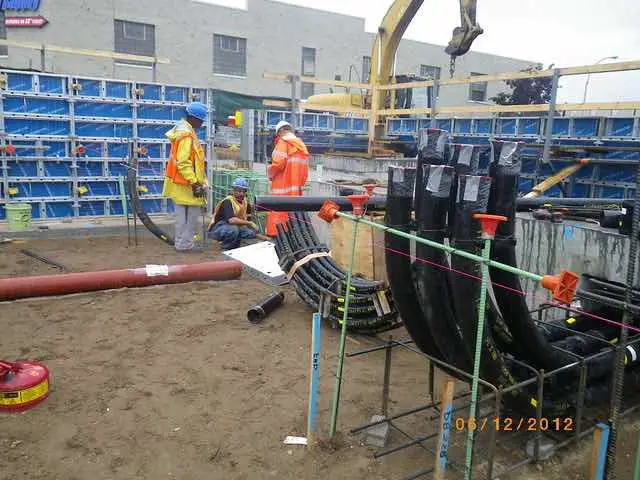
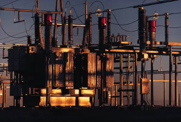
Substations contain equipment that
Conduit Installation
After determining the right approach to laying wires, a good amount of engineering work is involved in determining the following:
- Type of Wire and its Size (Ampacity)
- Conduit Size
- Number of Bends in a Conduit
- Conduit Terminations at Junction Box
1. Type of Wire and its Size (Ampacity)
- In direct bury applications, cable insulation is an important parameter to consider. They should be rated to handle both
heat generated by the current and resist degradation due to moisture content in the soil. - Wires installed inside conduits can get away with resistance to high heat due excellent insulation properties (Example: THHN insulated). However, know that when more than three wires are installed in a conduit, they will carry less current than they are capable of when only one is installed. This derating happens due to excessive heat surrounding the wire.
- Besides the resistivity of the wire (which changes with the diameter), the insulation on the wire determines the amount of current it can carry. Calculating the exact current carrying capability of the wire, a.k.a. its ampacity, is quite cumbersome. An easy and reliable means of determining the wire ampacity is by looking up the National Electrical Code (NEC) book. This book furnishes the ampacities of various wires subject to certain limitations. You must follow them carefully for proper application.
2. Conduit Size
- Since conduits bend and twist in different directions to reach a junction box (j-box) or a cable trench, there is a limitation to the number of wires that can be installed in it. Squeezing more wires than what is recommended in the NEC book can jam them, making cable pulls a nightmare job.
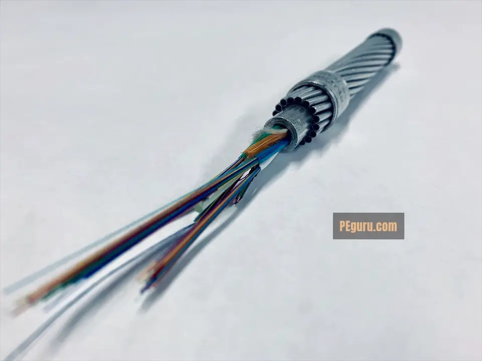
- Sometimes the engineering application determines the conduit size. For example, a conduit that needs to carry the fiber optic cable is oversized due to the cables’ fragility.
3. Number of Bends in a Conduit
- The common practice in the industry is to not make more than a total of 360º bends from the opening at one end of the conduit to the other end. When not made in the field, the bends are created by installing prefabricated conduit elbows.
- If the conduit run is long and making many bends is unavoidable, installing hand-holes in the path of the conduit will help. Hand-holes provide the provision to pull the wire from incoming conduit before it is inserted into an outgoing one.
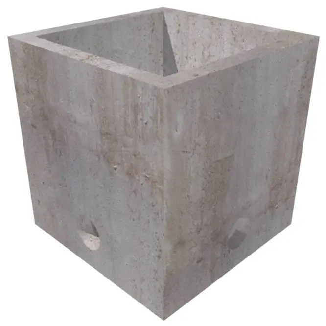
- Another item to keep in mind: small conduits up to 2” (inches) can be easily bent in the field. Larger ones (3” and above) are tough, therefore conduit elbows need to be ordered in advance with the required bend radius.
4. Conduit Termination at the Junction Box
- Conduits terminating on top of the j-box need a box adaptor. The adaptor provides a good setup to prevent weather elements from ingressing the j-box.
- Conduits terminating at the bottom surface of the box can be fitted with a threaded conduit with washers and a locknut. Locknut and box adapters should prevent wires from chaffing on the box edges when moved.
- If the conduit is metallic then a locknut integrated with a ground bushing is used. The ground bushing enables the bonding of
metallic conduit to the j-box’s ground bar. - Flexible metal conduits (
sealtite andliquidtite variety) are good substitutes for the stiff ones for runs between the j-box and the ones stubbing up from the ground. It compensates for the engineering errors made when the stub-ups (in the foundation or earth) do not line up exactly under the j-box.
Cable Installation
- Not all wires can be placed adjacent to each other. For example, you cannot place an AC wire (from station service transformer or a power transformer) in parallel or close to a control wire – a wire, for example, that can trip a circuit breaker. Induced potentials due to AC can cause relays to mis-operate.
- Stray inductions can be prevented by shielding cables.
- Sometimes cable shields are not sufficient. See Grounding And Shielding Cables – Best Practices In Wiring Equipment In A Substation for more information.
- Therefore, as a precaution, a bare copper (ground) wire is run adjacent to a conduit carrying control wires.
Summary
- Determine correct cable size and its insulation based on the load it is feeding and the way it is installed.
- Determine conduit size based on the number of cables you want
installed in it. - Avoid making a lot of bends. If this can’t be avoided then install cable pull boxes or hand-holes to ease the cable installation.
- Avoid grouping AC power wires and control wires.
- Refer NEC codebook for information on topics discussed above.

Pingback: Outdoor Plastic Junction Boxes: Pros and Cons | Polycase
DETAIL METHOD OF STATEMENT FOR SUDSTATION CABLING