Are you sizing a lightning surge arrester for installation inside a substation? Electrical parameters: MCOV, TOV, and discharge voltage; should be on top of your list – for the correct application. If you are unfamiliar with these parameters, then check out the below infographic and the article, showing how to pick their values.
Arrester Terminology Context
First, you install arresters between energized lines and ground. Doing this gets you voltage ratings expressed in phase-to-ground, at the terminals.
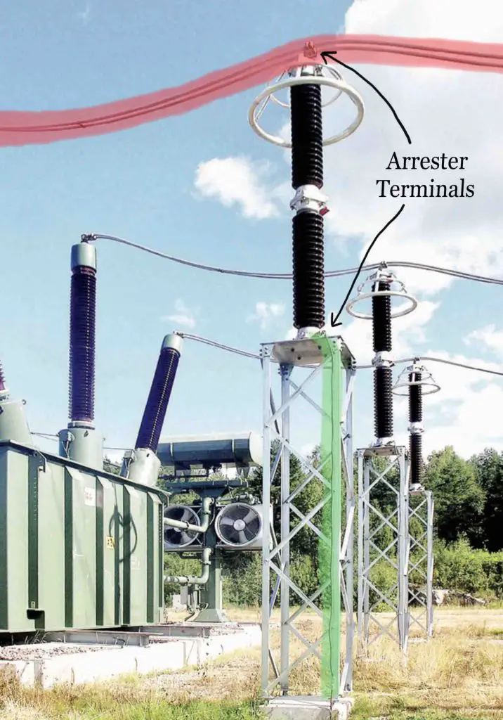
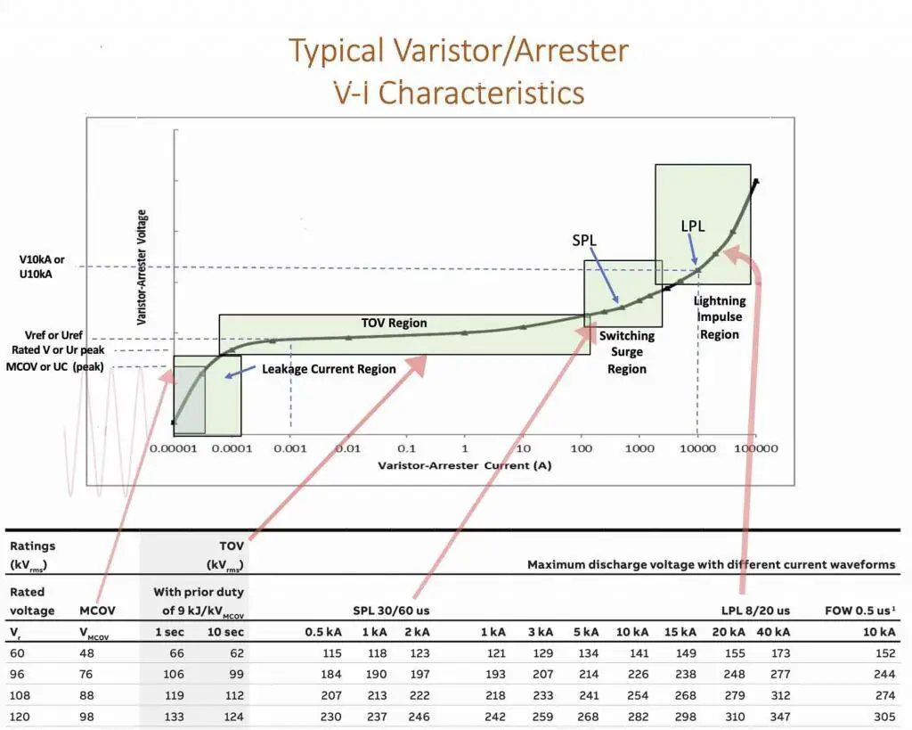
Next, take a look at the different terms utilized with the arrester specification and get a sense – at what point of arrester operation do they apply. Use the arrester VI curve for this purpose, shown below.
Electrical Properties
Rated Voltage or Duty Cycle Voltage Rating
An archaic term, typically associated with silicon carbide arresters, describing the peak voltage for operation. For Metal Oxide Varistor (MOV) type arresters, start with MCOV rating shown below.
Maximum Continuous Operating Voltage (MCOV) Rating
It is a phase-to-ground voltage rating above which the arrester operates. Consequently, pick a rating that is higher than your maximum (phase-to-ground) system voltage. However, how high would you choose? Here’s where Temporary Overvoltage comes into the picture.
For a list of all system nominal voltages and the maximum range, look-up NEMA C84.1 standard.
Temporary Overvoltage (TOV) Rating
The power grid is subjected to temporary over-voltages, described in detail in IEEE 142 – Grounding standard. This is not the same as a lightning strike or a switching surge. Its severity is much lower and, depending on the duration, does not warrant an arrester operation.
Among the many things that can cause TOV (line faults, load rejection, loss of ground, transformer in-rush, etc.), system grounding dictates how severe it will be.
In North America, the high voltage transmission systems are three-wire with the source neutral either solidly grounded or grounded through a low impedance reactor. The medium voltage distribution system is typically a four-wire multi-grounded system. Medium voltage industrial facilities typically have high impedance grounded systems.
Do you know how your system is grounded? Knowing this is important because we have convenient multipliers (shown in the table below) to calculate TOV and pick a rating from the spec sheet that exceeds this calculated rating.
| Type of system | Ground fault factor |
| Four-Wire Wye Multi-Grounded Neutral | 1.25 |
| Three- or Four-Wire Wye Solidly Grounded Neutral at Source | 1.4 |
| (High) impedance grounded systems | 1.73 |
| Delta and Ungrounded Wye | 1.73 |
EXAMPLE:
Pick-out an arrester with regards to TOV for a 138kV_{L-L} source grounded system with solidly grounded transformer neutral.

SOLUTION:
Available TOV for this particular system =
\frac{138}{\sqrt{3}}\times1.4 = 112kV_{L-G}
From the table in the Figure 2 above, an 88kV_{L-G} MCOV arrester (with 119kV - 1sec & 112kV - 10sec TOV) is adequate as long as the TOV does not persist beyond the timeframe indicated.
Knowing the actual system TOV magnitude and its duration is possible. Relay application engineers who can analyze the event data can provide this information. Combining this fact and the system neutral grounding method, you should be able to pick an arrester with TOV rating higher than the available system TOV. When no such data exists, it is prudent to pick arresters whose TOV capabilities equal the full phase-to-phase magnitude i.e. use the 1.73 multiplier. However, when you do this, watch out for the discharge voltage!
Discharge or Residual Voltage Rating
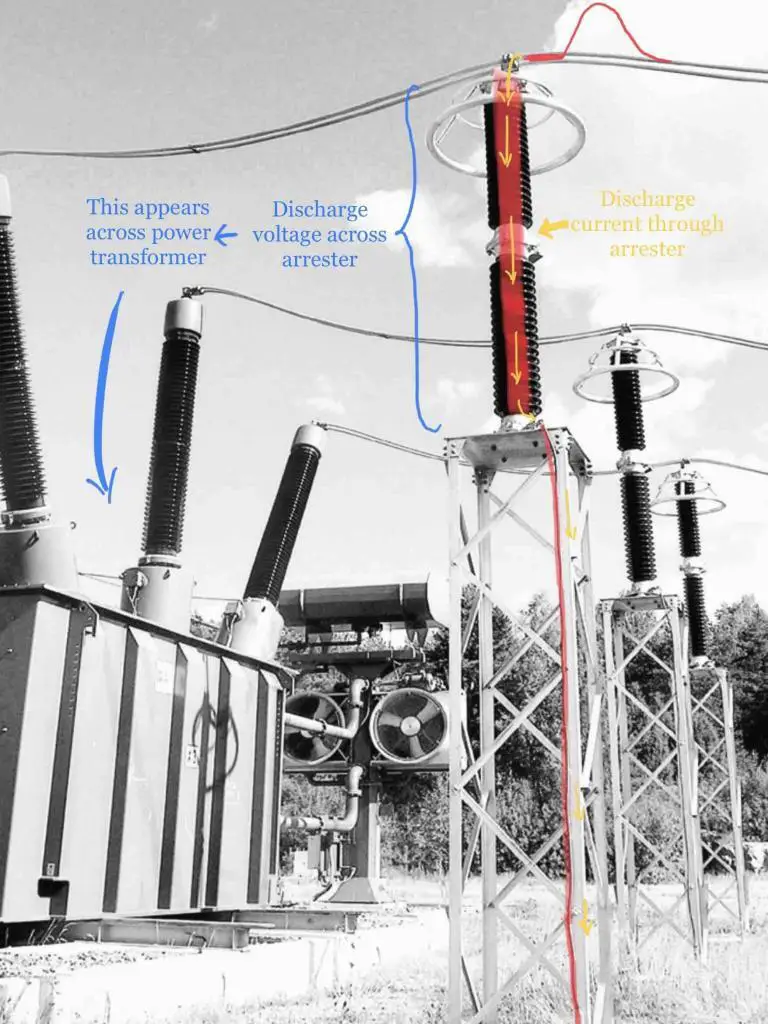
This voltage appears across arrester terminals when it operates. Consequently, the same voltage magnitude appears across the protected equipment. For correct application, it needs to be lower than equipment BIL (plus any margin.)
Following IEEE C62.11 guidelines, the arresters are tested using different shapes and durations of current impulses. If you do not know what the discharge current magnitude is (at the point of installation – for the lightning impulse), pick the 10kA column, and verify the discharge voltage corresponding to the MCOV voltage. The lower the discharge voltage, the better.

Continuing with the above example, an 88kV MCOV arrester when subjected to a 10kA lightning impulse generates 254kV discharge voltage across arrester terminals.
This is acceptable considering this rating is well below the adjusted BIL rating of a 138kV piece of equipment (520kV).
For details on Lightning Protective Level (LPL) and Switching Protective Level parameters, check out this resource.
Energy Handling Capability
The MOV blocks tend to leak a minuscule amount of current at operating voltage, generating heat in the process. When the arrester operates, depending on the discharge current magnitude and its duration, more heat is generated.
Arresters manufactured with high energy handling capability can dissipate heat better and resume normal service following a severe operation. Under-rated arresters cannot.
Arrester Special Installation
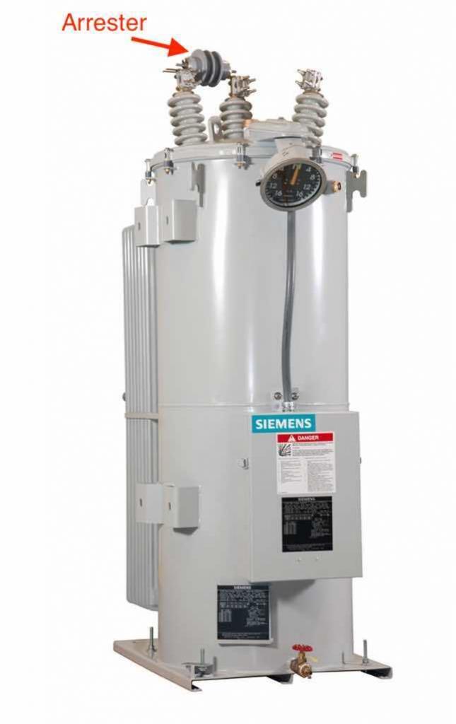
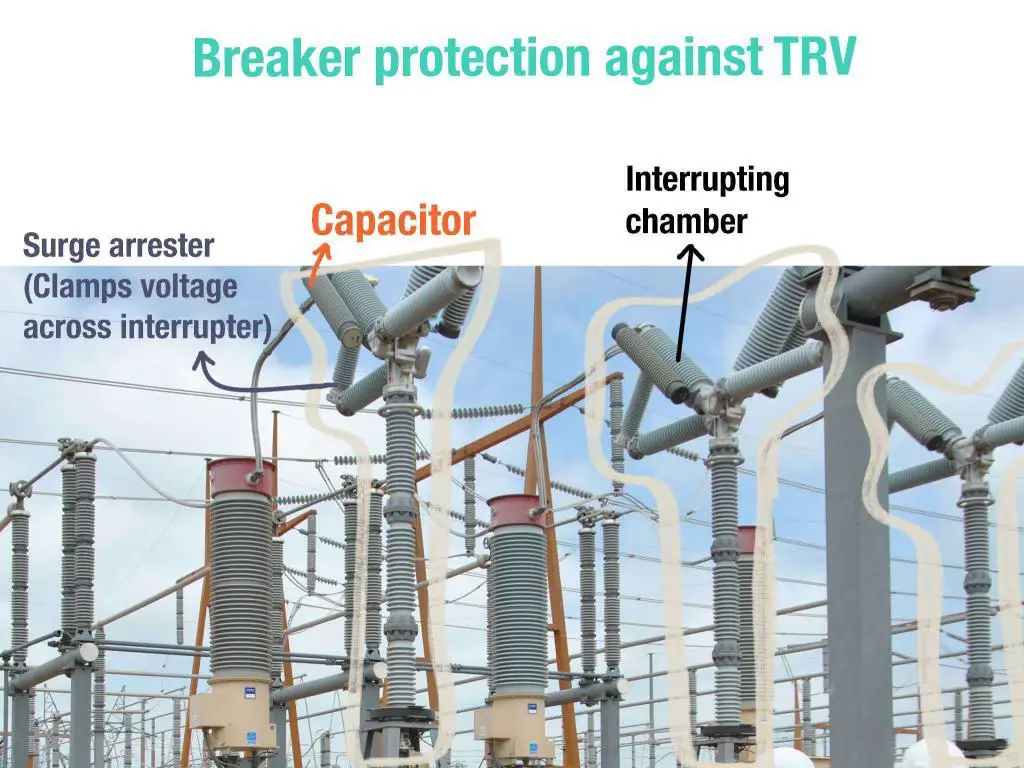
In specific applications, you mount the arrester in-line on the equipment terminals (no connection to the ground). This is quite common on extra-high-voltage live-tank circuit breakers. In the medium voltage system, it is found on voltage regulators, between source and load terminals. The manufacturer determines the ratings in these cases.

Is the system Fault level a consideration when sizing Surge arrestors?
13.2kV 31.5kA for 1 second bus.
No. Arresters are sized for lightning strikes and switching surges.
This is tolerance in voltgae. IF tolerance is +- 5% than max voltage would be 5% more than niminal voltage.
Hi, why the LI and SI are defined with different impulse profile than what the Switchgear and other equipment are tested?
For example the lightning impulse is 1.2/50 micro seconds for Switchgear and why here it is defined 8/20 micro seconds? Thanks in advance.
To protect low-voltage installations against power surges caused by lightning surge protection devices (SPDs) should be installed as far upstream as possible. Great info you have shared here.
Why Max. Voltage is considered 5%Vnom??
It’s coming from industry standards.
Transformers have 5 tap settings A, B, C, D and E. The transformer is set at tap C for the nominal voltage. Tap D is for a voltage 2.5% higher than Tap C (the nominal voltage) and Tap E is 2.5% higher than Tap D making the maximum system for the transformer 5% higher than Tap C (the nominal voltage). Similarly, Tap B is 2.5% lower than Tap C. Tap A is 2.5% lower than Tap B (5% lower than Tap C).
This is tolerance in voltgae. IF tolerance is +- 5% than max voltage would be 5% more than niminal voltage.