One problem that is pervasive in the power grid and not well understood is called the Transient Recovery Voltage (TRV). When a short-circuit due to a fault in high voltage or medium voltage system is switched-out by a circuit breaker, the voltage across the breaker poles rapidly increases; as high as twice the operating voltage. See picture below.
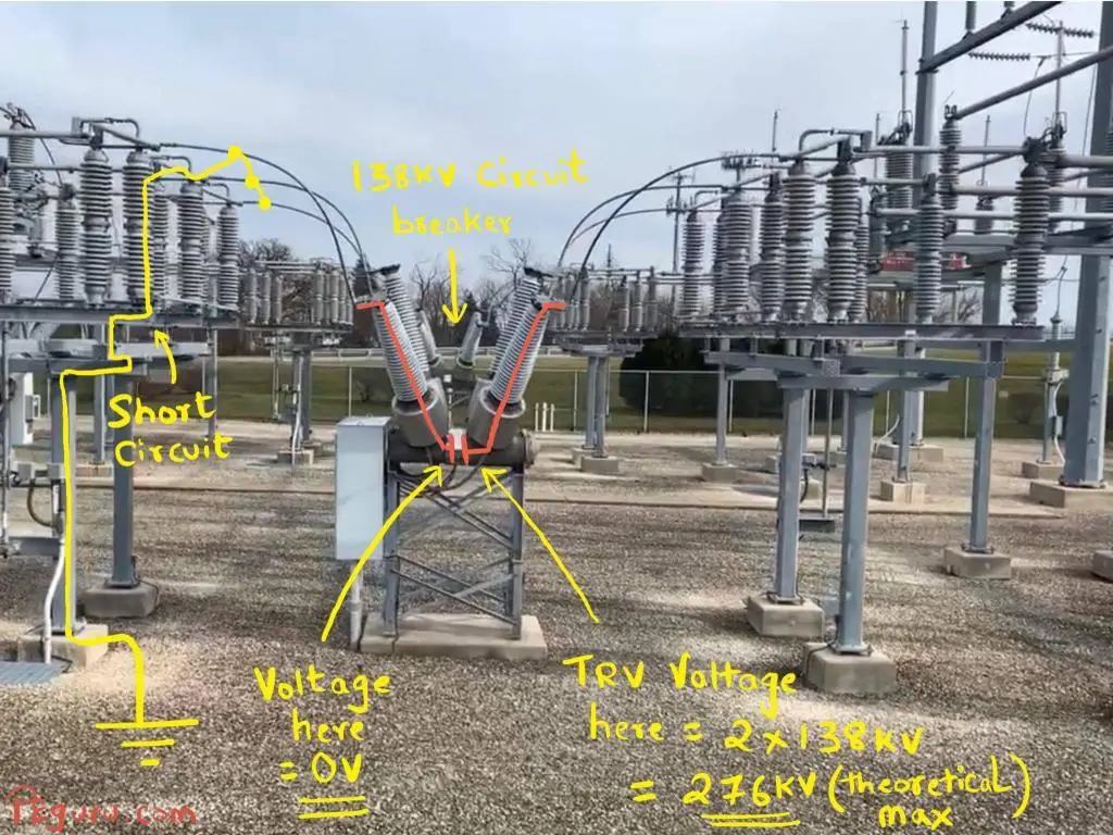
Although the interrupting chamber inside the breaker has enough dielectric strength to withstand the elevated voltage, the rate at which the recovery voltage rises (also known as RRRV) can overwhelm the insulating medium. This leads to arc re-ignition at the poles and eventually breaker failure.
Let’s split hair here and understand the underlying cause of TRV. I’ll present this issue in two steps.
Step 1: Inductance and Capacitance
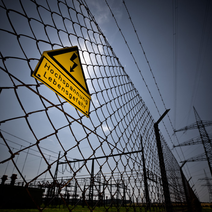
When a layman sees pieces of power grid (shown in picture below), it is natural to process them as mere steel structures and energized wires.
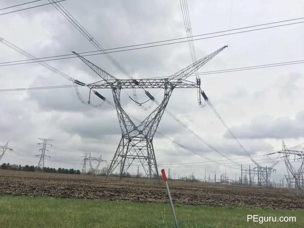
However an electrical engineer must visualize it as inductor L, capacitor C, and resistor R. Parameters L and C are born as a consequence of energizing the wire. How?
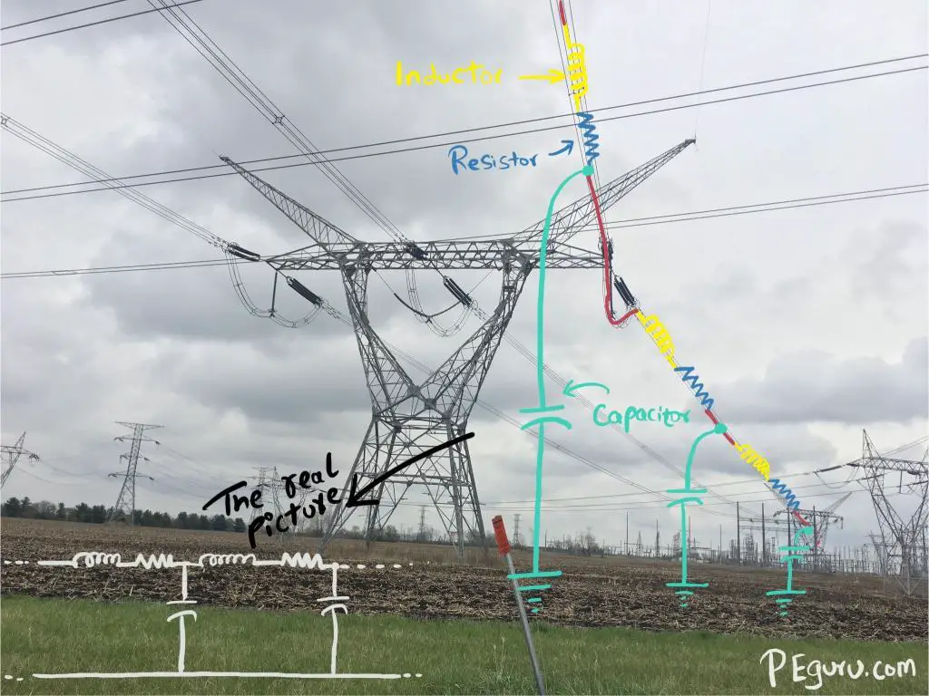
AC current passing through a wire or a piece of rigid metal produces magnetic field. This field is alternating just as its source and thereby induces voltage back onto the same wire such that it opposes any sudden change in current. A physical manifestation of this push-back effect occurs when you drop a magnet through a non-ferrous metallic tube, shown below. The magnets fall is retarded by the magnetic field generated by the copper tube.

We looked at the effects of alternating current. The alternating voltage on the line creates its own effect – the capacitance. Remember, earth conducts electricity. It is the return path for unbalanced currents (when neutral is unavailable) or fault currents (involving earth). So two conductors separated by dielectric (air, in this case) is essentially a capacitor. Now because there is a path from energized line to ground during normal operation (through a capacitor), the capacitor draws a leading current called the charging current. This current flows even when one end of the line is open.
The last piece is the resistor. The resistance is that of the material used for routing power, usually aluminum or copper. It always exists regardless the line is energized or de-energized.
Step 2: L-C circuit behavior during a short circuit
Now that we have established R-L-C components in the grid, how do they behave when the breaker operates?
Figure below will be used to explain.
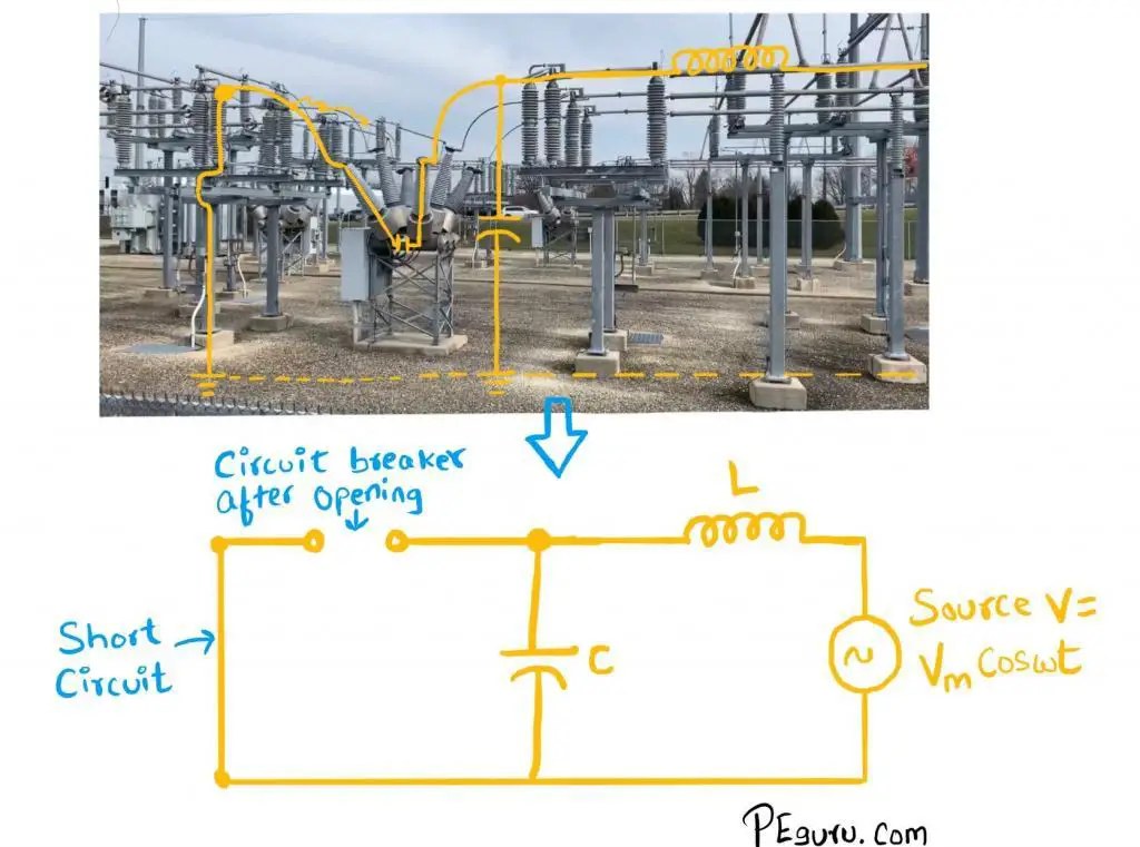
Let’s begin with following conditions
- A solid 3-phase fault close to the circuit breaker is assumed – produces the most severe TRV.
- Resistance R is ignored for now.
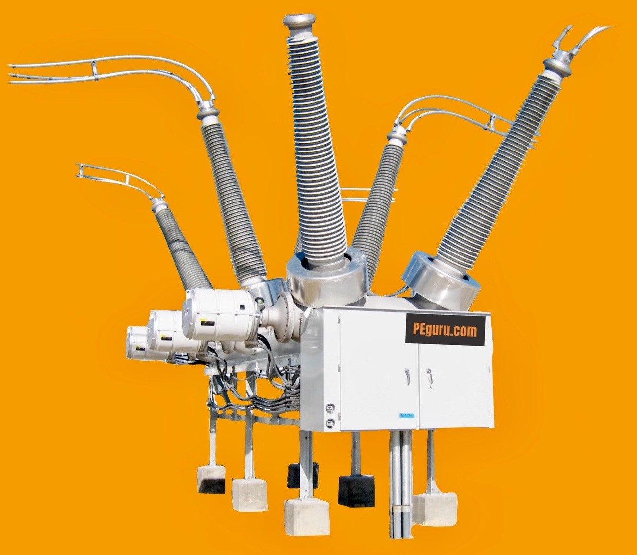
- The line to ground capacitance close to breaker is considered. This capacitance exists due to capacitance in bushings (specifically condenser bushing), current transformers, adjacent power transformer,
etc .
At the instant a short-circuit occurs, before the breaker opens, the line to ground capacitance is shorted-out. However as the breaker opens, it draws an arc. As soon as it is extinguished, the source voltage starts to charge the line to ground capacitor through the system inductance.
The consequence? The voltage across the breaker poles is equal to the system nominal voltage plus voltage created by the natural response of a L-C circuit. There are two circuits at play here now. Let’s look at L-C circuit specifically.
In a lossless L-C circuit, the voltage oscillates indefinitely. The energy stored in capacitor discharges and in-turn charges the inductor – storing energy in its magnetic field. Once inductor is charged, it discharges to charge the capacitor. This cycle looks like below. See KhanAcademy for additional details.
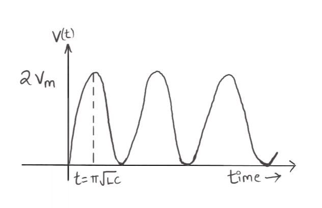
The voltage equation for a L-C circuit is given by
V(t)=V_{m}[1-cos\omega_{0}t] ……….[1]
where the first peak 2\times V_{m} occurs when \omega_{0}t = \pi
The frequency of oscillations is given by
f = \frac{1}{2\pi\sqrt{LC}} ……….[2]
The L-C circuit in the power grid is not lossless, however. You have resistance due to copper or aluminum material. This resistance ends up damping the oscillations down. The peak magnitude of TRV too is subdued by several factors. One of them is the type of fault. We have considered 3-phase fault, however, asymmetric faults like line-to-ground or double-line-to-ground makes the fault current cross zero axis before the system voltage reaches its peak. The other reason could be the way the system is grounded – low impedance or high impedance.
When you superimpose damped L-C oscillations over operating voltage at its peak, the resultant waveform looks like below.
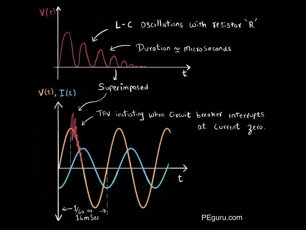
Note the difference in the duration of oscillations. The capacitance near the 138kV breaker is typically in pico-farads and inductance in micro-henrys. When you plug these into equation [2] above, it generates frequency in kilo-hertz. This high-frequency transient occurs at such a rapid pace the nominal 60hz power frequency looks constant in comparison. It is precisely, for this reason, a breaker not equipped to handle TRV – fails.
Specifying circuit breaker to overcome TRV
The TRV performance for breakers have been well established in several ANSI/IEEE standards, namely:
- IEEE C37.04 – Standard rating structure for AC high voltage circuit breakers
- IEEE C37.06 – Standard for AC high voltage CBs rated on a symmetrical current basis
- IEEE C37.011 – Guide for the application of TRV for AC HV circuit breakers
For instance, for a 145kV (maximum voltage) rated circuit breaker in an effectively grounded system, the TRV it must handle at rated interrupting rating (40kA or 63kA) is 215,000 volts. The Rate of Rise of Recovery Voltage (RRRV) is 2,000V/microsecond.
Well, are these ratings adequate? The answer to this is driven by the public utility’s experience with breaker failure associated with TRV.
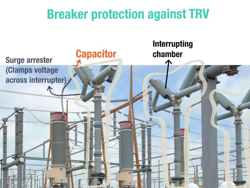
There are areas in the power substation where TRV is acutely severe, for instance, when switching a capacitor bank or a lightly loaded EHV line. Breaker manufacturers don’t just rely on IEEE guidelines here. A detailed study is conducted to determine the size of an external capacitor and resistor, which are used to proactively tame the L-C circuit. These are then mounted across breaker bushing or interrupting chamber—more on this in another post.
Summary
AC systems create complexities by introducing inductance and capacitance. In a L-C circuit, a circuit breaker interrupting a fault is subjected to high frequency – high voltage magnitude transients. This article presented details of how this happens and why it is catastrophic for the circuit breaker.


Hello Aleen,
Thank you very much for presenting the TRV concept in such a simple and practical way. I really appreciated the tower photos showing how the equivalent circuit is made up. Thank you for adding a real element to the theory. Love your work.
Regards,
Melissa
Sir,Thanks a lot for presenting a very educative phenomena of TRV and its effect on Circuit breakers.
Sir, Kindly explain the ill-effect of Back-to Back Switching-in of Capacitor banks on the circuit Breakers.I shall be highly obliged for this.
Thanks and regards.
K.K.Murty
Former Chief Engineer (testing & Commun.)
MPPTCL, Jabalpur,INDIA
One way is that,,, complete physical analysis of resistor and capacitors at infinestimal value and how much voltage they prdouce at all fault types.
Then guide the designer of circuit breaker keep (nominal voltage and lc component voltage) in our range.
Because TRV can’t be more than 2Vm.
Or
Use capacitance uptp nano farad instead of pico farad. It will incrase charging current but it can be handled.
Nano farad capacitance decease the oscillation. So it will appear later when trv gone.