Ground Grid Installation
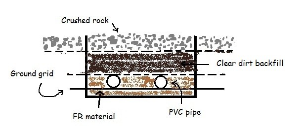
Ground grids are installed at a depth such that the fault currents flowing in from the above grade steel structures are easily dissipated into the earth. This is accomplished by:
- Drilling ground rods (at strategic locations) to a depth where the soil resistivity is low.
- Connecting the ground grid to the rods so that the grid can access the low resistivity soil.
Typically the ground grid is installed at 36” below grade while the ground rods are driven into the soil to a depth of 10 feet. These depths are approximate and vary with design standards of various electric utilities. At locations where the soil resistivity is high, ground wells are accessed.
But Why Ground?
The purpose of grounding is to prevent electric shock and to mitigate overvoltages that can damage equipment. In substations, the high voltage lines carry alternating currents. If you are familiar with Faraday’s induction principle, a time varying flux (due to alternating current) induces voltage in an adjacent conductive equipment.
This means the steel structures in and around live equipment will pose a shock hazard. Even the fence enclosing the substation will have induced voltage when high voltage transmission lines pass overhead. It is essential to ground all above grade conductive structures to mitigate the shock hazard.
Types Of Shock Hazard In A Substation
- Touch Potential Hazard
- Step Potential Hazard
Touch Potential Hazard
As the name suggests, it is a shock hazard brought on by touching the steel structure inside the substaton. Ofcourse, this happens when the equipment is improperly grounded.
Step Potential Hazard
When there is more fault current flowing into the ground grid than the grid can dissipate, the ground potential of that area rises. This is also known as earthrise. If you walk inside the substation – barefoot, during this abnormal earthrise, every step you take will zap you. This occurs due to potential difference between your feet – one foot on a higher voltage surface than the other.
Touch and step potential hazard can be analyzed in a grounding study using IEEE Std. 80 or IEC 479-1. A geotech survey of the substation needs to be performed to obtain the soil resistivity data to enable this study.
Summary
- Grounding of steel structures inside the substation is important to prevent shock.
- The ground grid should be designed to dissipate the available fault currents and prevent localized earthrise.


How often the grounding grid need to be inspected for an integrity check yearly or twice a year.
Visual inspection is tough since the grid is buried. A more reasonable approach is to test the grid (4 point wenner method or other) at different points inside the substation. The points where the readings are low is where you dig and fix the copper connections.
How often do you do these tests? Not sure. Each Owner needs to determine the frequency. One major factor to consider is corrosion.
How corrosion affects copper varies from location to location and what other bare-metals are nearby.
IEEE 80 puts the recommended grounding grid depth at 300-500mm (12-18inches) per Section 9.2.b)1)
Could you clarify why you have mentioned above typical ground grid is installed 36 inches below grade.
Another question is would it be okay to have the ground grid depth a little higher or lower in depth at select portions of a substation for convenience (Eg. if the ground grid is a little deeper near the control house to assist with the conduit entrance into the control house (to have the conduit running above the ground grid there); would that be okay.
Can you please include relevant photos here and there? You are already spending so much time writing an article, why not make it visual too.
Thank you.
This Website helps me how to solve the per-unit system.
Thanks.. very useful and easily understandable..