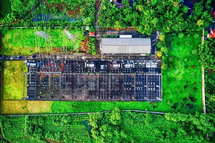
What does it take to design a masterpiece of a substation? Quite a bit, honestly. In this article, I will share 18 substation design calculations or studies that will set you up to create a beautiful substation. Here’s the list.
System Planning
Short-circuit study
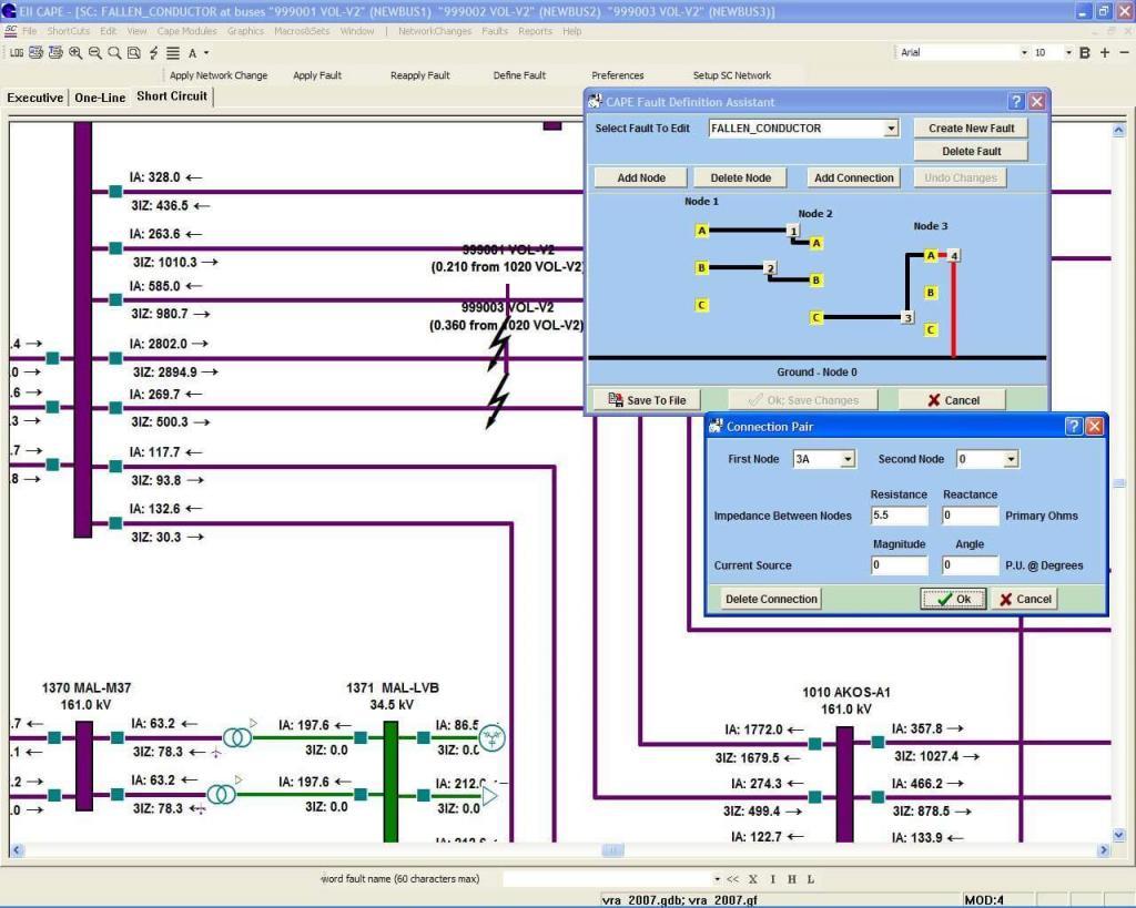
| Why conduct short-circuit study? |
| Hundreds, if not thousands, of When a short-circuit occurs – generators pump current into the fault. – motors (which store energy in the magnetic field) backfeed into the fault. Under-rated equipment subjected to this sudden current in-rush may catastrophically fail. |
| Outcome of short-circuit study |
| The study furnishes momentary and interrupting fault current magnitudes along with impedance to the fault location (either in symmetrical components X1-X0 or X/R ratio). More information here. You should use the results to – Procure substation equipment rated to withstand, and when designed for, interrupt fault current – Determine trip setting for relays – Perform other studies such as bus calculations and ground grid study |
Load flow study
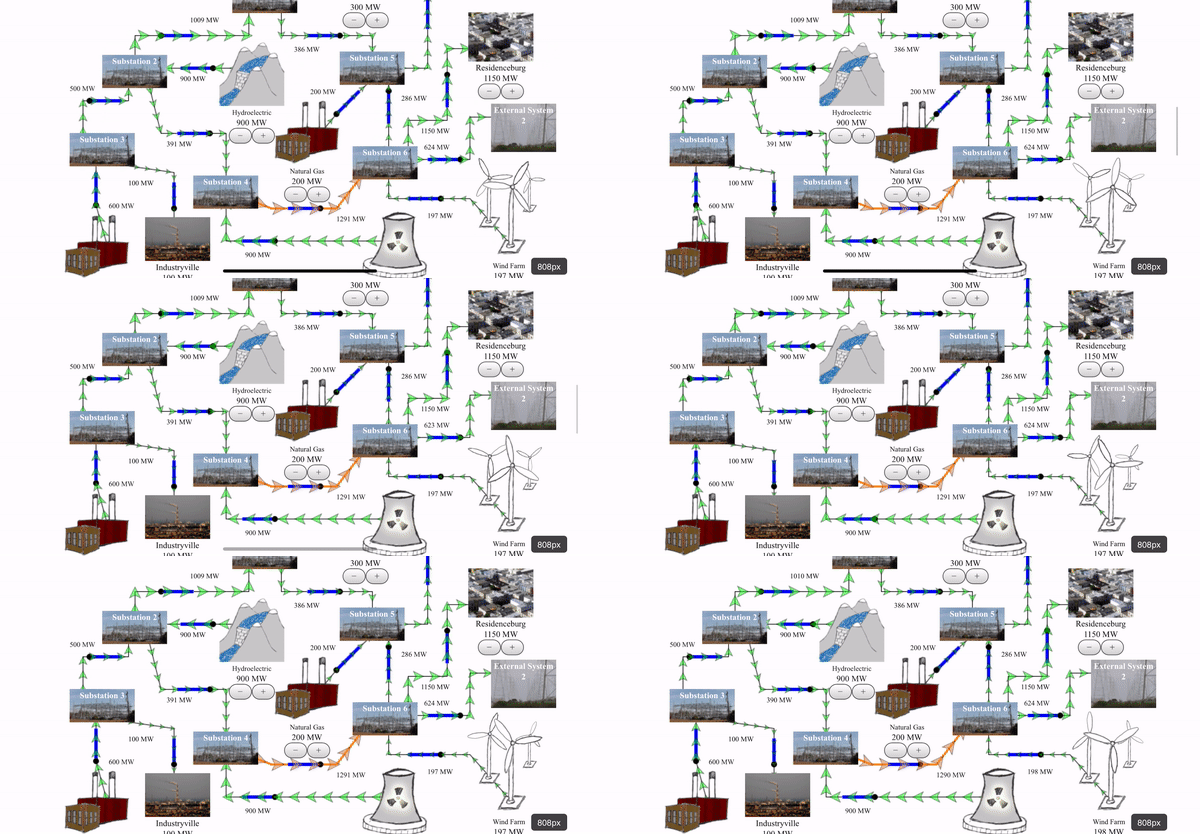
| Why conduct load flow study? |
| The grid operates in equilibrium. When load increases, the equilibrium shifts to a new high, with generators ramping up to keep up. This increase in power (consequently the continuous current) overheats underrated equipment and causes the insulation to deteriorate or fail. Furthermore, some amount of power is lost as heat on the transmission lines. This results in a voltage drop at the receiving end of the line. |
| Outcome of load flow study |
| The study furnishes voltage drop, continuous current, and power factor at different nodes in the grid. You should use the results to – Procure substation equipment rated to withstand continuous current – Determine trip MVA for transmission lines – Determine pickup settings for overcurrent relays – Determine transformer LTC settings – Correct power factor using capacitors Note: Minimum ratings are also standardized by the Regional Transmission Operator (RTO). For example, this design criteria document for transmission owners (under PJM) mandates continuous current for line terminal equipment. If the load flow study prescribes a lower rating, you should discard the results in favor of RTO requirements. |
Insulation coordination study
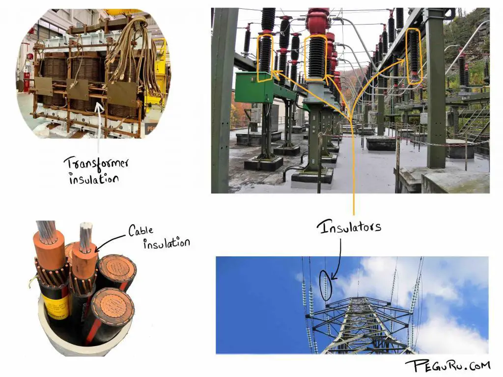
| Why conduct insulation coordination study? |
| The power grid is subjected to lightning strikes and temporary over-voltages. A lightning strike occasionally carries greater than 1 million-volts, 100 kilo-amps, and 20 giga-joules of energy. How “beefy” should the insulation be to survive this? You could spend a lot and over insulate or, when the |
| Outcome of insulation coordination study |
| Choose standardized BIL rating (Basic lightning impulse Insulation Level) for the substation from IEEE 1313.1 standard. If you are choosing lower insulation level, pay close attention to the ratings of surge arrester and its install location. Results are incorporated in the following drawings: – General arrangement plan drawing (because BIL rating dictates phase-phase and phase-ground clearances) – General arrangement section view drawing – Equipment installation detail drawing Note: There are no formulas to calculate BIL. It has been established based on experience and lab tests. At 345kV and above voltage, a switching surge has |
Electrical – Substation Design Calculations
Protection and control analysis
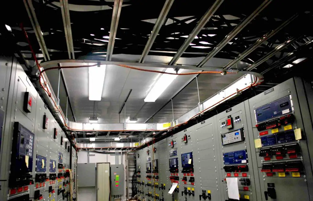
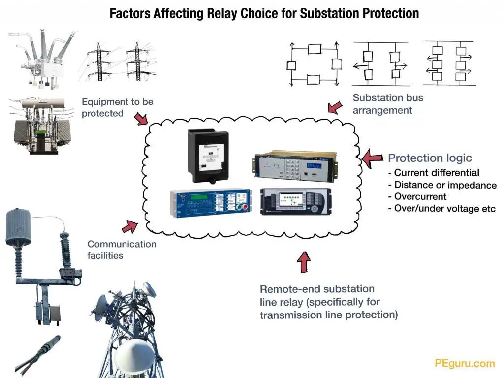
| Why conduct protection and control analysis? |
| Power substations contain expensive pieces of equipment. Some form of protection is required to prevent them from going up in smoke. Protection of modern substations is implemented using microprocessor relays. Relays are required to: – Trip and isolate only the faulted zone. In other words, m – Maintain grid stability by shedding either load or generation (thus keeping voltage and frequency within tolerances). Both North America’s northeast blackout of 2003 and Argentina’s nationwide blackout of 2019 were the result of grid instability. |
| Outcome of protection and control analysis |
| – Specify protection and control logic for the substation equipment. – Specify SCADA and communication system for automation, annunciation, and remote control purposes. – Create relay settings that coordinate with other relays (in the station and at remote-end). – Create relay settings that generate high-speed tripping to disconnect generators or loads (during abnormal conditions) to maintain grid stability. Results are incorporated in the following drawings: – Oneline, AC schemes, DC protection schemes, relay panel wiring drawings, SCADA and communication drawings – Control building layout – Relay panel front views |
DC system – battery calculations
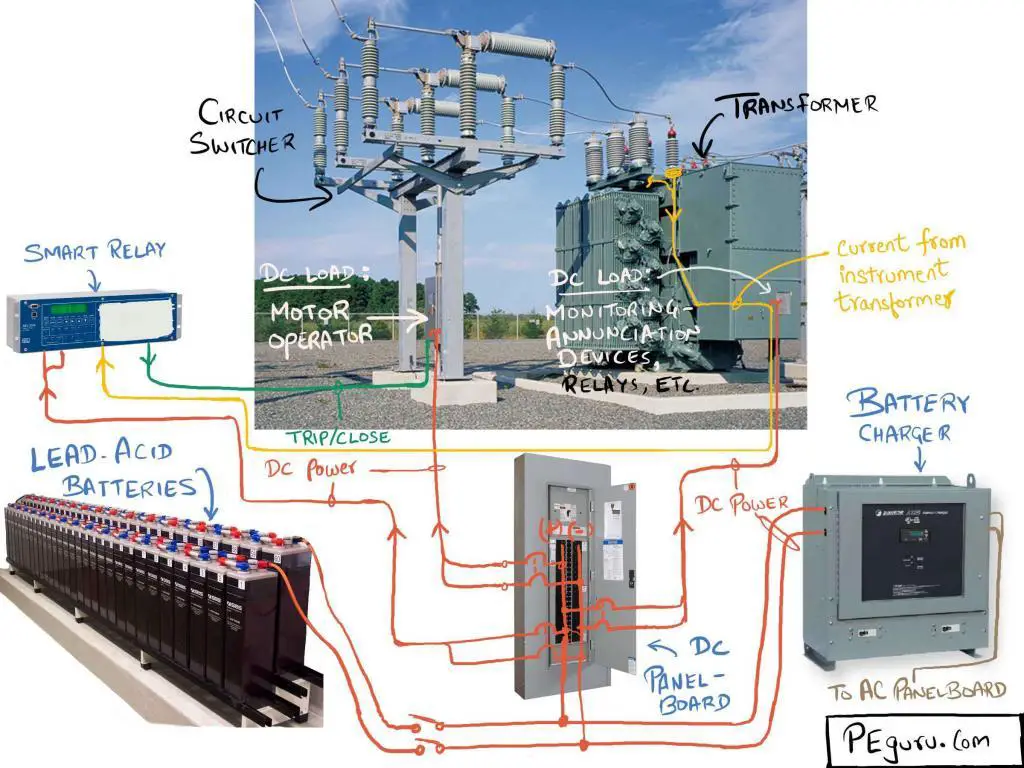
| Why conduct battery calculations? |
| – Motors which operate high voltage switch and ones that charge the spring inside the circuit breaker – Microprocessor relays inside the building and inside the power equipment all work using DC power. A battery that not only packs enough energy but also provides the discharge characteristics to operate substation equipment is needed. |
| Outcome of battery calculations |
| Specify batteries with enough amp-hour capacity to support the continuous load for 8 hours and momentary load (such as breaker and switch operation) for a minute or more. The popular battery chemistry in the industry is lead-sulphuric acid. Specify battery charger that is capable of charging the battery. Results are incorporated in the following drawings: – Station DC power oneline |
AC system – auxiliary power transformer calculations
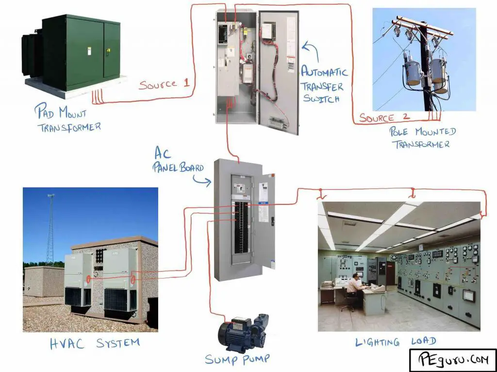
| Why conduct auxiliary power transformer calculations? |
| Not all loads in the station rely on DC power. The HVAC system, transformer fans, lights, cabinet heaters, lift-stations/sump pumps, battery charger, etc require AC power. |
| Outcome of auxiliary power transformer calculations |
| Specify auxiliary transformer capable of supplying the demand. Results are incorporated in the following drawings: – Station auxiliary AC power oneline |
Ground grid study
| Why conduct ground grid study? |
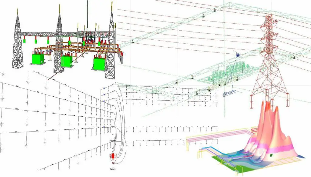
| A lightning strike on tall power transmission structures is inevitable. When this surge is buried into the earth, it needs a path to dissipate. If this path is unavailable (due to high resistivity soil, for instance) the ground potential rises at the point of contact. This is a hazardous situation. Anyone walking in this area is subjected to an electric shock because of the potential difference developed between feet (with reference to Figure 8, one foot on red peak and the other on blue valley). This is called step potential. The same concept applies to touch potential. |
| Outcome of ground grid study |
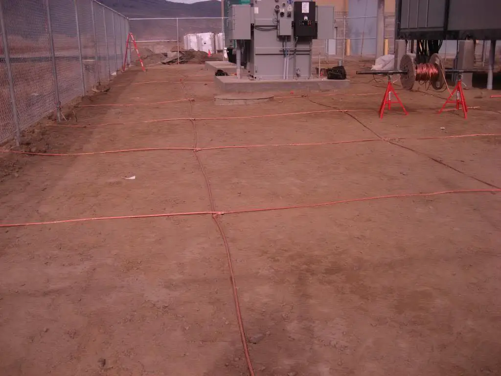
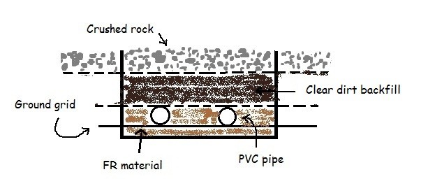
| Install mesh grounding system as shown in Figure 9 to create an equipotential surface. Drive ground rods into the Because earthing is impacted by soil resistivity, in certain cases, the native soil needs to be replaced to get the desired results. Results are incorporated in the following drawings: – Ground grid plan drawing – Ground grid installation details drawing |
Lightning protection calculations
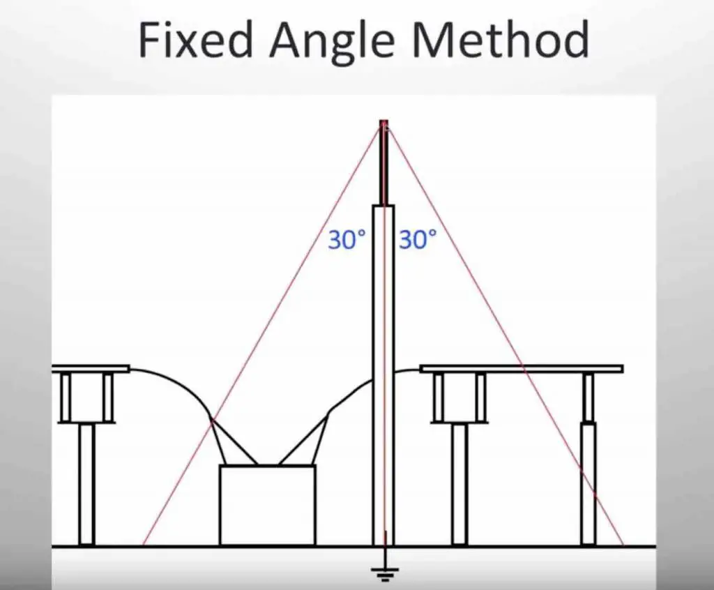
| Why conduct lightning protection calculations? |
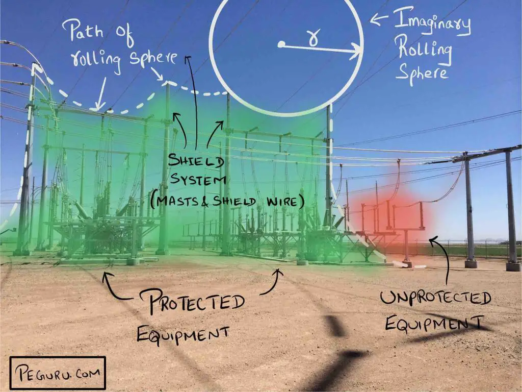
| Substations need a shield to protect itself from lightning strikes. |
| Outcome of lightning protection calculations |
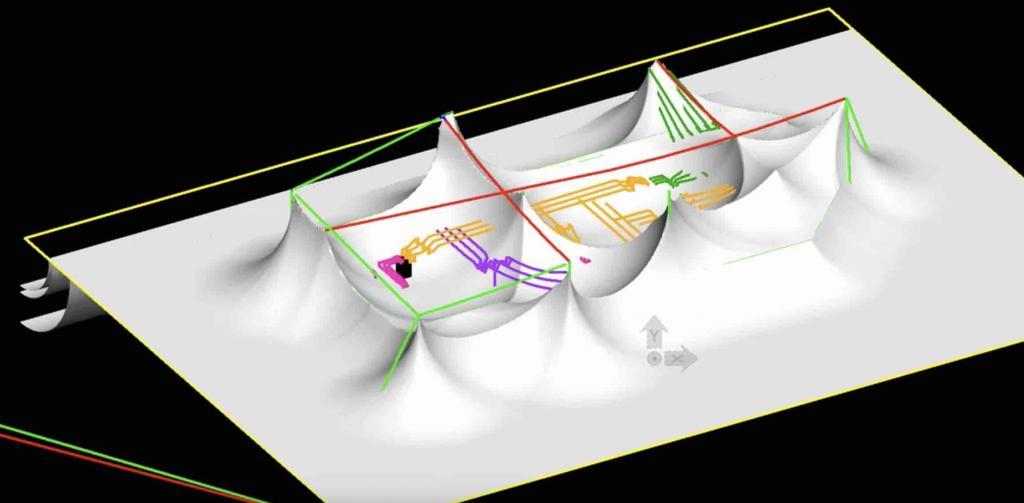
| Install a combination of lightning masts and shield wires that provides adequate lightning strike coverage. It should be noted, creating 100% coverage is impossible. Therefore a probability study is conducted to determine the likelihood of a lightning strike on the unprotected equipment. If the risk is acceptable then the coverage is reduced or not installed at all. Results are incorporated in the following drawings: – General arrangement plan drawing – General arrangement elevation or section view drawing |
Lighting calculations
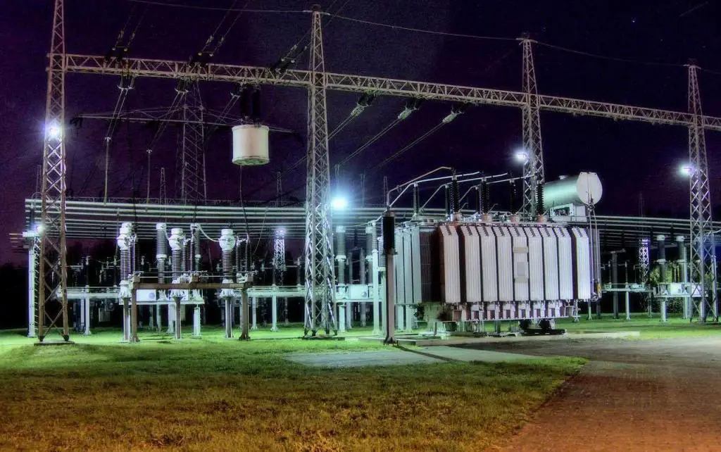
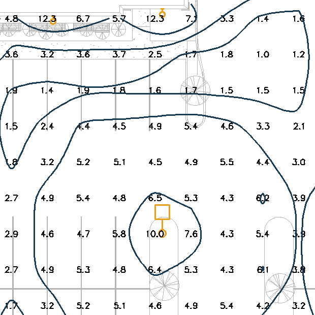
| Why conduct lighting calculations? |
| Substation security and safety of personnel is important. A well lit area serves this purpose. |
| Outcome of lighting calculations |
| The height and angle of Results are incorporated in the following drawings: – Substation lighting plan drawing |
Voltage drop calculations
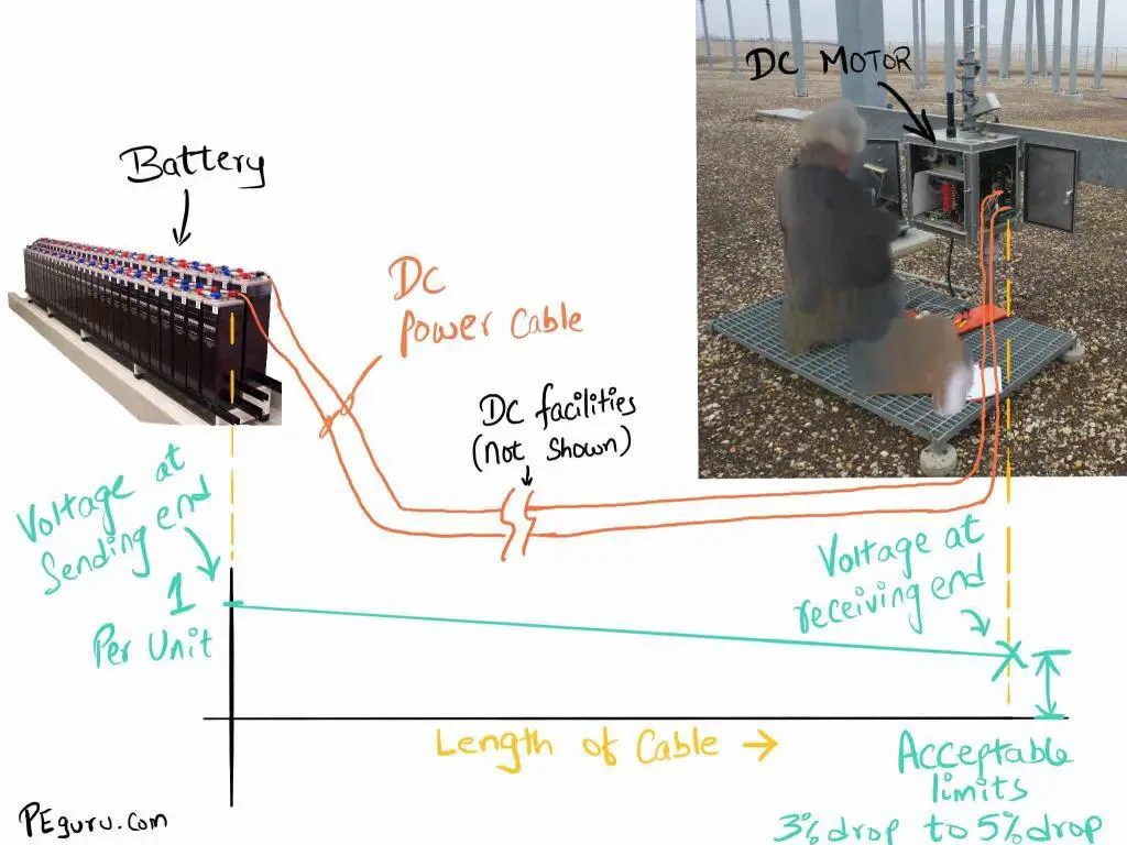
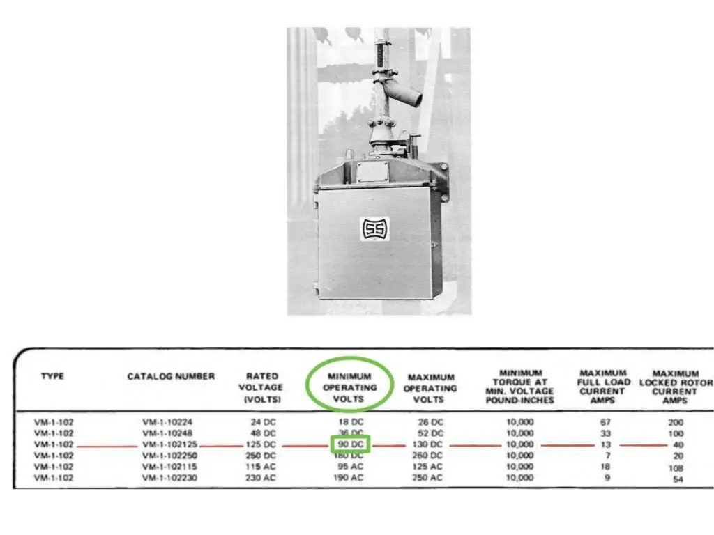
| Why conduct voltage drop calculations? |
| Motors or coils that operate massive substation equipment require a |
| Outcome of voltage drop calculations |
| Determine wire size (1/0AWG or #2 gauge or #6 gauge etc.) such that voltage developed at the receiving end is within equipment working limits. Results are incorporated in the following drawings: – Cable schedules – Wiring drawings |
Conduit fill calculations
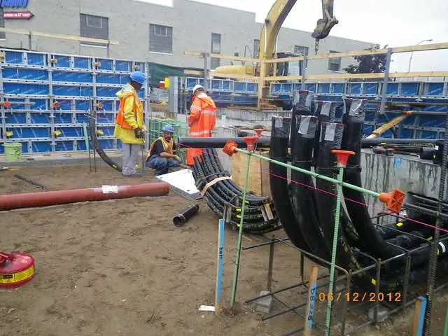
| Why conduct conduit fill calculations |
| This is fairly straightforward. Pulling more wires than what is possible will break below-grade PVC conduits especially at the bends. |
| Outcome of conduit fill calculations |
| Specify the quantity of wires that can be pulled. Install a combination of handholes or manholes or cable troughs to make cable pulling easy. Results are incorporated in the following drawings: – Conduit plan drawing – Conduit installation details drawing |
Civil / Structural – Substation Design Calculations
Land survey and site grading analysis
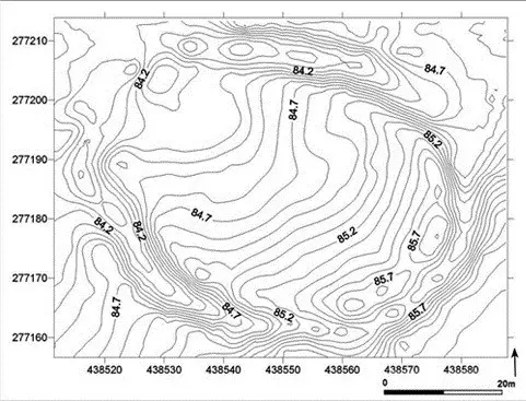
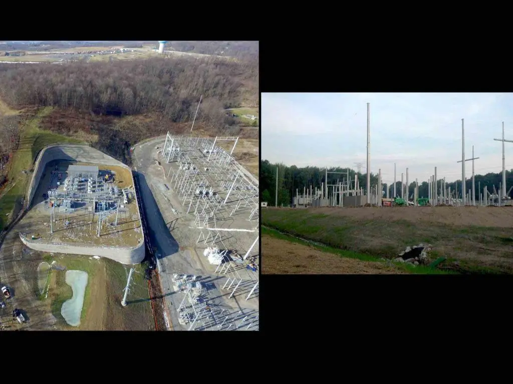
| Why conduct land survey and site grading analysis? |
| How much money is spent on building a new substation is largely influenced by the location. Cutting and filling the earth to create a flat property (in a mountainous area), creating the right slope to channel water away from substation, stormwater management, etc is an expensive affair. |
| Outcome of land survey and site grading analysis |
| Determine if the land is feasible for construction. Create a grading plan. Design drainage facilities like culverts, ditches, detention ponds, lift-stations etc, to handle stormwater. Create compensatory storage when building in a floodplain. Results are incorporated in the following drawings: – Site grading plan drawing – Site grading detail drawing – Property plan drawing |
Geotechnical investigation and foundation calculations
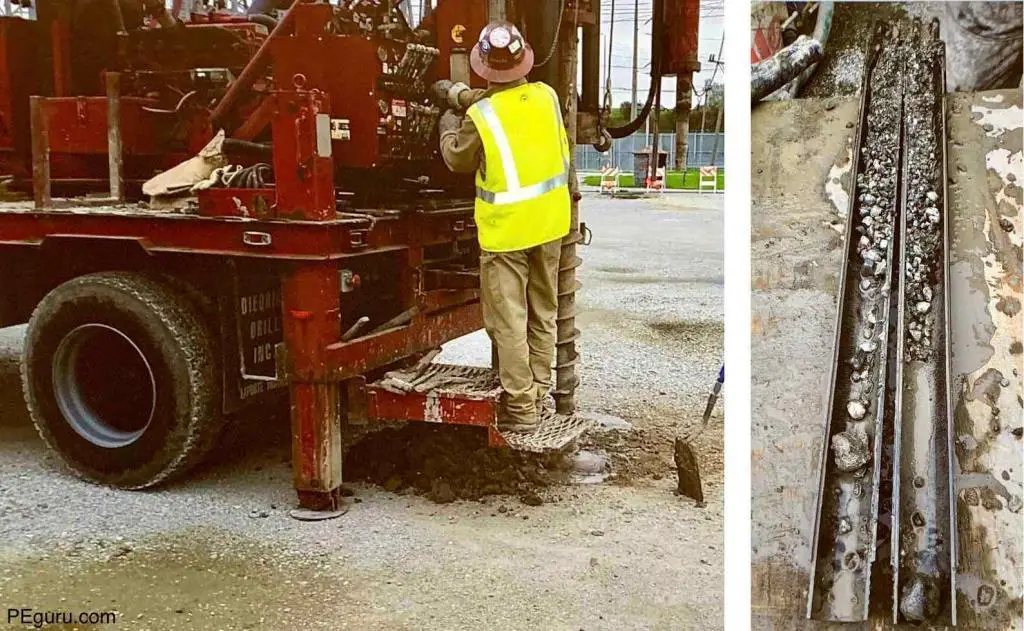
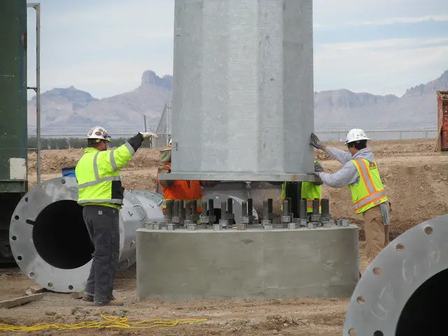
| Why conduct geotechnical investigation and foundation calculations? |
| Soil conditions play a significant role in the design of foundations. |
| Outcome of geotechnical investigation and foundation calculations |
| Geotechnical investigation reveals information on soil conditions, underground obstructions or hazards, seismic conditions, topography, etc. Learn more here. Based on this information: – Remediate contamination or other hazards in the soil. – Design foundations to mount buildings, steel structures, and substation equipment Results are incorporated in the following drawings: – Foundation plan drawing – Foundation details drawing |
Structural steel calculations
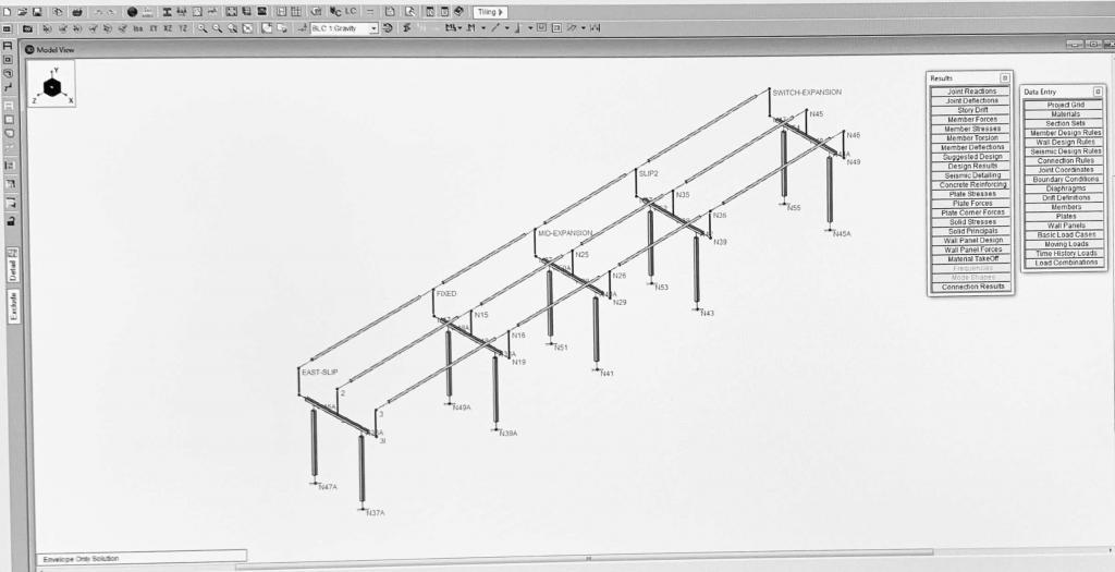
| Why conduct structural steel reaction calculations? |
| Structural steel is subjected to horizontal loads (line tensions, wind load, etc) and vertical loads (dead weight of equipment mounted on it, ice load, etc). |
| Outcome of structural steel reaction calculations |
| Specify steel structure capable of handling the horizontal and vertical loads. The legs of tall structures are also susceptible to aeolian vibration. Install adequate cross-bracing or vibration dampers to prevent this condition. Results are incorporated in the following drawings: – Steel framing plan drawing – Steel framing section view drawing |
Bus calculations

| Why conduct bus calculations? |
| As seen in the video, a piece of substation bus is subjected to extreme forces generated by fault current. A setup without adequate bus support and under-rated bus support insulators – will collapse. The study also analyses the effects of wind loading, snow loading, bus material, etc. |
| Outcome of bus calculations |
| The goal would be to insert enough bus supports to stabilize the bus (considering all the forces acting on it). Also, specify extra high strength insulators where necessary. Results are incorporated in the following drawings: – General arrangement plan drawing – General arrangement section view drawing |
Miscellaneous – Substation Design Calculations
Transformer noise calculations
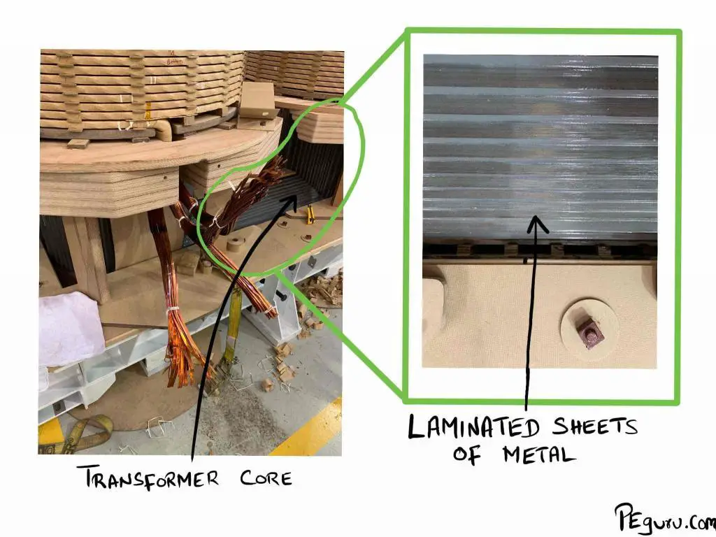
| Why conduct transformer noise calculations |
| Power transformers generate audible noise, typically greater than 60db. This can be over-bearing. If the substation is located in a city, the constant hum from a new transformer may be unacceptable by local ordinances (especially at night time.) |
| Outcome of transformer noise calculations |
| Specify standard sound transformer if the noise generated is acceptable. Otherwise, mitigate the noise using either sound walls or by specifying low-sound transformer. |
Harmonic analysis
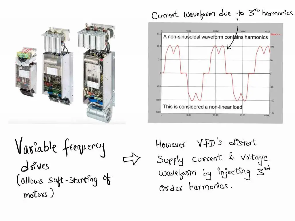
| Why conduct harmonic analysis? |
| Non-linear loads (characterized by changing impedance as it draws power) injects harmonics into supply voltage and current. The resulting waveform is not smooth but one marred by spikes and dips. When these propagate into the high voltage system, they damage power transformers and affect the power quality of other customers. |
| Outcome of harmonic analysis |
| In substations where harmonics are present, specify equipment to filter them out. The methods and means of doing this are mentioned here. |
Fire protection study
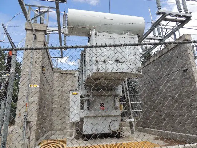

| Why conduct fire protection study? |
| Short circuit at any location inside the substation generates an incredible amount of heat, as high as 40,000F – enough to cause the |
| Outcome of fire protection study |
| Install firewalls. Fireproof the control building, not just sidewalls but penetrations in the floor as well. Passive fire protection |
That’s it, you have read every single study that’s conducted when building a new substation. Any thoughts? Drop them below.
Author credit: Sanity checks on the civil / structural section provided by Nauman Khan – Structural Engineer, PE.

THANK YOU FOR YOUR SHARING
Tank you , do you have some software for bus bar calculation. Example substation 225/33kV wit 2 lines, 2 transformer 100MVA, cupler and duble busbars omnibus.
thank you very much for sharing this article. it’s very very useful for me to understand the design process of a HV substation. thanks and best regards.
Dear Aleen,
I would like to have an idea about the volume of protection of power transformer by surge arrester. and do you have any simulation software to use?
Best regards,
Mohamed
Well done! Substancial knowledge for electrical engineers starters!
Regards
I am so impressed by this article. Thank you so much for the effort and sharing this article. As a result of this article, I learned a lot more from reading this article than taken power system course because of the on-point explanation and clear visual illustration.
Good morning.
I subscribed this morning to your website and immediately thereafter there came up a link to download the pdf ebook “
Power Substation Design Calculations – A Checklist of 18 Studies for Engineers to Consider”
Erroneously I closed the window and then I can’t find that link anymore, not it is in my mailbox.
Is it possible to send it?
Arc flash analysis is missing.
I thought about it but chose not to include it. However, I feel you are right, it should have been in the list. One factor affecting the choice of relay is arc-flash. And then there is also arc-flash rated switchgear and all the bells and whistles that come with it. Thank you for your input.
Just the other day I needed to calculate inrush currents and freq of transient of cap bank to correctly spec a breaker to switch cap bank
I was contemplating on including the transient recovery study in this article. However, I decided against it because 18 seemed like a nice number to end the list at.
excellent work