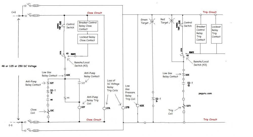
Understanding the breaker scheme is important if you plan on designing a substation. Quite often, it is overwhelming to make sense of the entire scheme at a glance. Therefore, the figure below depicting a circuit breaker scheme will be used to simplify and explain various elements of the breaker’s design and its control.
Forms of Contact
Before explaining what each device in the scheme does, understanding the different forms of auxiliary contact is necessary. Every breaker comes fitted with an auxiliary switch. It is mechanically linked to the breaker’s trip-close mechanism. Within the auxiliary switch case you can have either form ‘a‘ contact (a.k.a. 52a per ANSI) or form ‘b‘ (a.k.a. 52b).
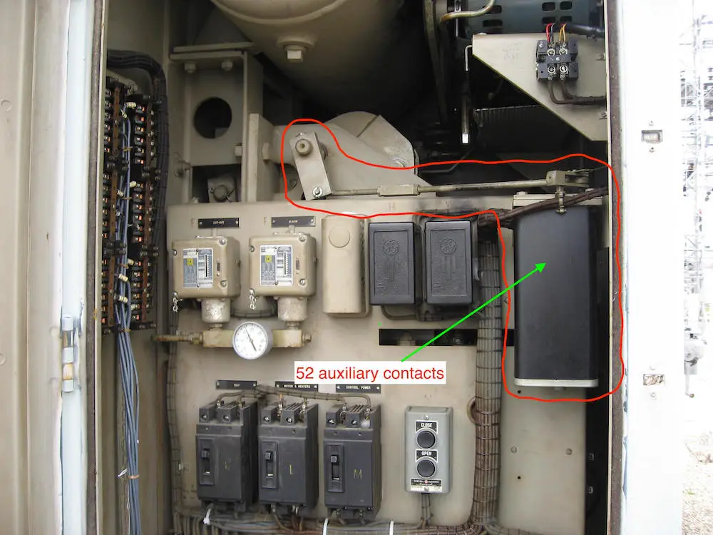
A form ‘a‘ contact represents a Normally Open (N.O.) contact. Thus when the breaker is open, its 52a contacts are open. When the breaker is closed, the 52a contacts are closed. The 52a contact follows the status of the breaker.
A form ‘b‘ contact represents a Normally Closed (N.C.) contact. It operates exactly opposite of what an ‘a’ does. When the breaker is open, the 52b contacts are closed. When the breaker is closed, the 52b contacts are open.
With the 52a contact in the trip circuit (as shown in the scheme above), once the breaker opens, this contact opens too. Now no matter what the relays do, the trip coil is isolated. On the flip side, with the breaker open, the 52b contact in the
Apart from breaker auxiliary switch contacts, you will see relays such as anti-pump relay 52Y, low gas relay 63X, under voltage relay 27,
Circuit Breaker Trip Scheme
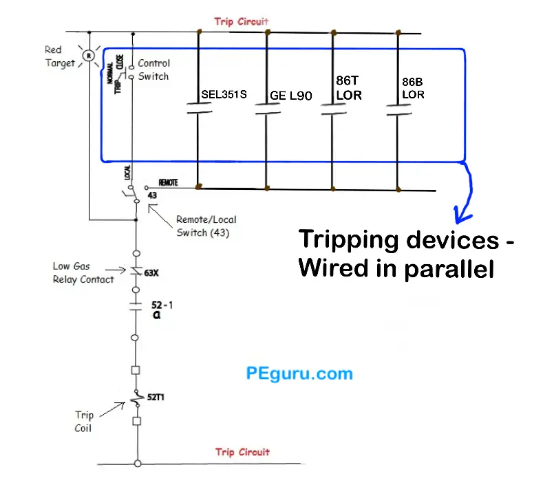
For the trip circuit, you must wire the tripping relays’ ‘a’ contact in parallel. See Figure 2. Therefore when
Modern power circuit breakers employ Sulfur Hexa-Flouride (SF6) gas to extinguish an arc. Without adequate gas i.e. reduced interrupting capability, a flash-over can occur inside the tank. To prevent flash-overs due to low gas, breakers are fitted with ANSI ’63’ relay. Tripping of breaker is cut out by this relay’s contact.
Most modern circuit breakers are specified with two trip coils. Energizing either one trips the breaker. Since a good amount of redundancy is built into the protection and control of a power system, it is not uncommon to see all primary relaying in the system tripping trip coil 1 and the back-up tripping trip coil 2.
At this point, I hope the reader has grasped the strategy of series-parallel placement of relay contacts.
Let’s look at other relays and switches from the trip circuit of our breaker. The 27B under-voltage relay trip coil is connected across the same DC source as the one feeding the trip circuit. When this supply is interrupted, the 27B relay coil is de-energized, operating its contacts. In our breaker, we are not blocking
Target Devices
Target lamps are used in circuits to convey certain conditions. With the breaker closed and energized, the red lamp illuminates to indicate a live breaker. When the breaker opens the green lamp illuminates – the circuit complete with 52b contact switching from open to close.
Now, you may notice the red target lamp is connected in a way that will essentially short out the tripping relays and trip the breaker. Not surprisingly, this is not the case. The target lamps have enough resistance in them (~200 ohms for a 125VDC circuit), limiting the current that can energize the coil.
Circuit Breaker Close Scheme
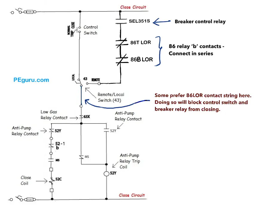
For this circuit, you must wire breaker control relay’s ‘a’ contact in series with a string of 86 lockout relay ‘b’ contacts before you hit the anti-pump relay in the
Modern breaker control relays are programmed to check for synchronism. That is, before the breaker is closed, the relay checks the phase angle of source and load side voltage of any one phase. If the angles are out of sync, the relay logic will not allow its close control contact to operate.
The close circuit also has contacts from the Motor Switch (MS). The motor is used to charge the spring that trips-closes. The motor switch contacts don’t allow the breaker to close until it finishes its job.
Details on how to develop a protection scheme
Alright! Enough theory. Want real world design implementation? Then checkout the ebook below. Industry popular 138kV Siemens SPS2 breaker scheme used. Relaying oneline for two different substations created from scratch to explain what trips, closes, and blocks close. Thank you for supporting this blog.
Circuit Breaker Control Scheme Aleen Mohammed
- Learn how to create trip and close scheme for a high voltage circuit breaker. Not just theory but practically implemented.
Anti-Pump Relays
To prevent inadvertent multiple closing operation, breakers are fitted with anti-pump relay (52Y ANSI designation). Assume a scenario where a fault persists on a line, and a person is attempting to close a breaker on it. Although the person presses the close button for a second or two, for the breaker which operates in cycles, this duration is an eternity. With the close button pressed, the breaker attempts to open and close multiple times. Since the motor in the breaker is not rated for continuous duty, serious damage can occur.
On a final note, keep in mind that not all relays back in the control building can handle the momentary inrush current from the breaker trip coil. Case-in-point the SCADA control relays. Interposing relays like those manufactured by Potter-Brumfield are typically installed to act as the middle-man. So in our case, the SCADA relay trips an interposing relay, and this relay energizes the breaker trip coil.
Most modern microprocessor relays, especially ones made by Schweitzer, can handle inrush currents up to 30Amps and thus can be wired directly to the breaker coils.
Summary
- Breaker scheme is a web of interlocked relays and switches.
- Breaker operation is controlled by relays and switches.
- Trip contacts are wired in parallel.
- Close contacts are wired in series i.e. breaker control relay ‘a’ contact followed by a series of LOR ‘b’ contacts.


Pingback: What is the purpose of an “anti-pumping relay”? – GrindSkills
Hi Aleen,
Great presentation as always.
I just wanted to ask if you could give some analysis of the Control Switches C,NAC and T,NAT contacts (use, operation, wiring).
Thank you.
Nik
Sir
I want to know troubleshooting on High voltage 11 KV panel s And 33 kv breakers and C&R panels.
Close,trip relay wiring
Relay settings
this article is very knowledgeable learn about Power Circuit Breaker – Operation and Control Scheme is very useful
many thanks
Very informative. Thanks for sharing. Keep up the good work.
Hi guys, quick question.
In a 22kV GIS switchger (e.g. ABB safeplus or Siemens 8djh) what is the std way of remote operation of the CB, via the protection relay o should I include a PAC for the operation of the CB? a list of pros and cons would be great!
in the specific scenario where a 3way RMU (LBs-CB-LBS) with only motorized cb is required, and everything needs to be monitored in this RMU, this meas CB stats, 3 position switch stats earth switch stats, lbs 1 stats,lbs 2 stats, SF6 alarm and others. should I use a PAC on this application? or if there are enough I/O in the relay should I go with that?
Thanks guys
Arturo
Choose protective relays for robust logic and faster operation. If you are falling short on output contacts, use self resetting tripping relays or lockout relays depending on what the protection is for.
For monitoring stuff, it doesn’t have to be a protective relay. Use your pacs or other devices for your SCADA system.
i am new in this field.pls make me understand in a easiest way…..