Inside the substation, conduits route the cables from the yard equipment to the control house. These conduits are directly buried and are routed to the cable ladder near the control room or are terminated at the nearest cable trench.
When showing a detail of the direct buried conduits on the design drawings, indicate
- Depth of burial.
- Location of ground grid relative to conduits.
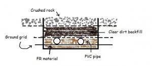
Direct Buried Conduit - Fire retardant material to bury conduits in. Example, sand.
- Clear dirt for back fill, on top of FR material.
- Mechanical tamping of the back fill.
- Cable markers or 2inch wide tape along the length of conduit.
- Crushed rock to top it off and installed flush with the adjacent rock
Sometimes these details are covered in the standard specifications pertaining to conduits and may not be shown on the drawings at all.


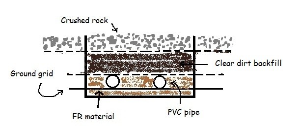

I should have marked the dimensions. So, I do concur with your observation. The conduits are usually installed 1′-6″ below the rough grade or 2′-0″ (~60cm) from the finished grade (6″ of crushed rock).
The ground grid should be couple inches below that. Btw, in the picture, the ground grid is represented by the solid black line.
Looking at your graphic it appears that the grounding grid is buried too deep or the conduit is not buried deep enough if it was placed per NEC at 60cm below finished grade.