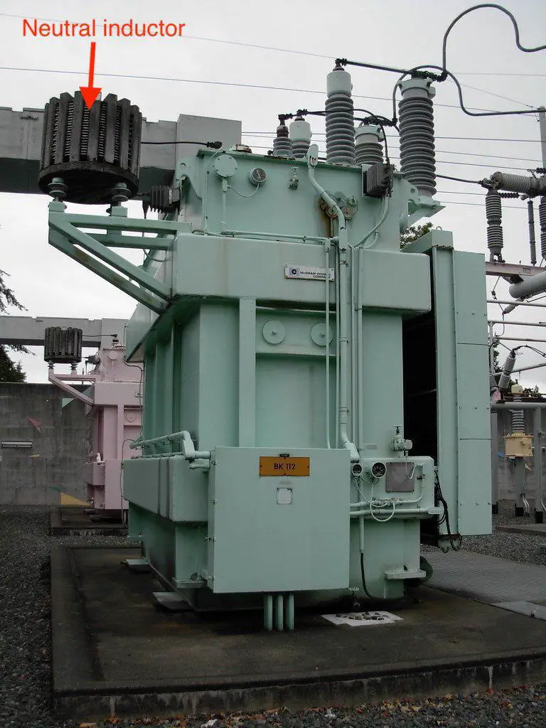
Short-circuit faults involving earth produce high fault current magnitude especially when the transformer neutral ground circuit is solidly grounded. Why?
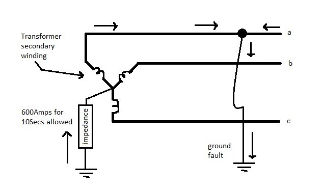
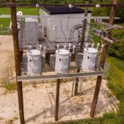
The neutral ground circuit in the transformer provides the return path for the fault currents. To limit this current, impedance – either in the form of a reactor or a resistor – is installed in the neutral circuit. See the figure below.
The table below provides the reasoning for choosing between resistor or reactor as the impedance in the transformer neutral circuit.
Resistor in the transformer neutral ground circuit
Image courtesy: Postglover |
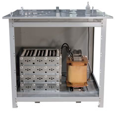
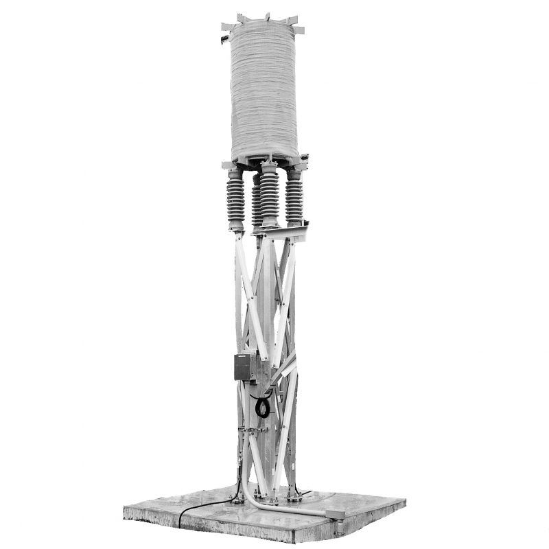
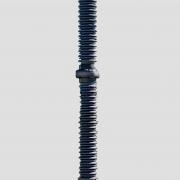
Reactor in the transformer neutral ground circuit
Image courtesy: Trench |
Pros |
|
|
|
Cons |
|
|
|
Transformer neutral ground impedance and transient over-voltages
Transient over-voltages are produced by arcing faults, not surges. The over-voltage occurs when the arc strikes due to a line-to-ground fault and charges the system capacitive reactance. When the arc momentarily extinguishes, the charge needs to dissipate. When the neutral ground resistor is used as the impedance, its resistance is usually less than the capacitive reactance, thereby allowing the voltage to discharge. However, when the reactor is used and when its reactive impedance is high (to limit ground-fault current to less than 25% of the three-phase current), the voltage cannot discharge. As the arc re-fires, the charge can continually build, thus creating the over-voltage.
Summary
If it is desired to limit the fault current to a really low magnitude using the actual resistance then a resistor is recommended. On the other hand, if several thousand amps of fault current is permissible in the system then the reactor is recommended. In either case, the reactor can be an economical solution. Keep in mind, we are talking about shunt air-core reactor in the transformer neutral for current limiting purpose. Series reactors, however, are expensive. The price of any neutral ground impedance device increases with the increase in the continuous current rating (for reactors), impedance rating, and time rating.
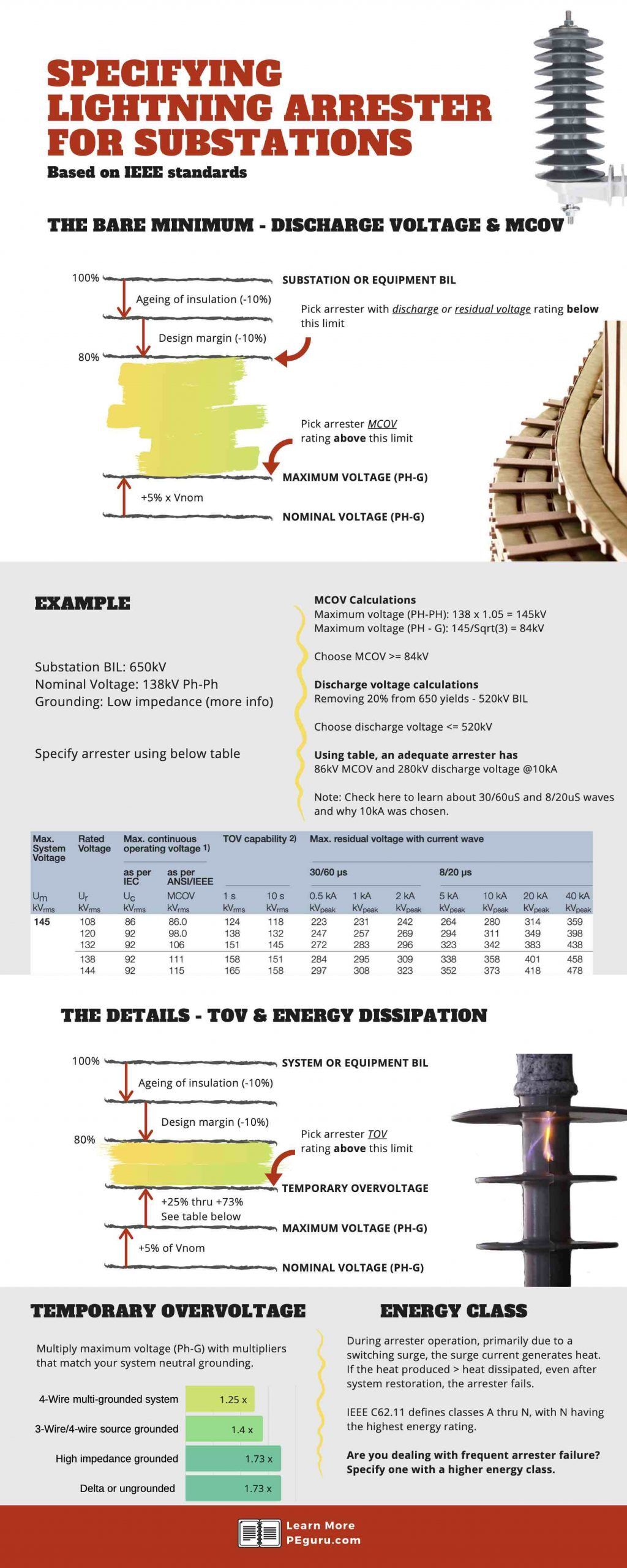
Are you interested in sizing an arrester based on system grounding? See below cheatsheet. Need full details that go with this? Check this PEguru article on arresters.


Idi,
I am working on a solar project and the transformer is three winding with burried delta and grounding resistor or reactor in the secondary. Transformer rating is 60MVA (138kV – 34.5kV – 13.8kV). The value of the grounding resistor is selected to be 10ohm to limit the SC current to 2.1kA. Three phase SC is about 10kA. The original design has determined a resistor. (which makes sense based on the comments above (25% – 60%). The comment from the client sugests to use a reactor (to limit the losses). Is there any standards that recommends where to use the resistor or reactor? I still beleieve that the resistor should be the solution, but i need to support my answer.
Thanks.
How do calculate neutral ground impedance for power transformer size 5000 kva , 13.8/4.16 kv , 60hz
I could not find anywhere information on the calculations to arrive at 25% or 60%. IEEE 142 only states X0=10X1 for 25% and X0=3X1. Do you have any idea on how to arrive to those numbers?
As with few things in power system design, it is very likely derived from lab tests.