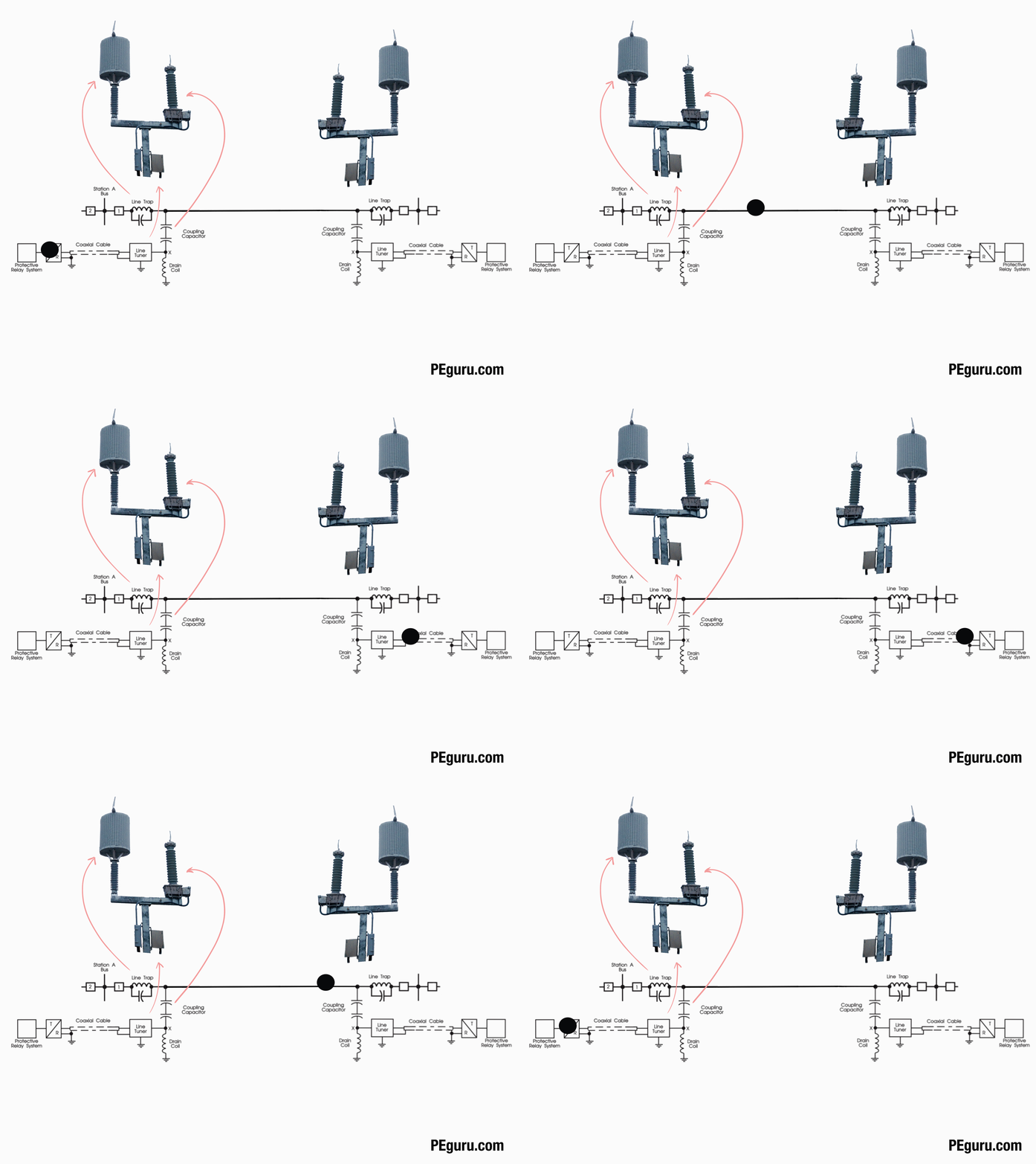
Pilot relaying refers to any relaying scheme employing a communication network between relays, at different substations, to transmit “trip or don’t trip” signal. The intent here is to trip the circuit breakers as fast as possible.
In the past, the relays communicated over the copper wire that directly tied them. These days we possess other options, described later in this article.
Rationale for pilot relaying
- Faster fault clearing time
- When compared to no pilot channel, the protection scheme exhibits increased security and dependability
- Enables high speed reclosing
- Simplifies relay coordination
Communication channel for pilot relaying
The relays utilize communication facilities described below.
Power line carrier (PLC)
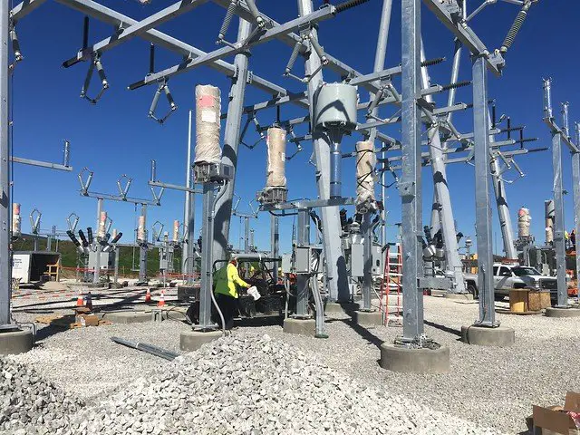
The communication path is the power line itself. A pilot relay, capable of generating a high-frequency carrier signal, couples the “message” to the high voltage line via a line-tuner and capacitor-coupled voltage transformer.
The pilot relay generates either
- On/Off carrier signal- (amplitude modulation) think of it as infrequent pings.
- Frequency Shift Keying (FSK) carrier signal – (frequency modulation) think of it as a persistent dial-tone you hear on the phone.

Fiber optic cable
Specific relays, fitted with high wattage laser, communicates through a single-mode fiber.
The fiber specified is either
- OPGW on transmission towers
- ADSS cable on distribution pole or underground.
The fiber optic cable is directly hooked to the protective relays on either end of the line. When forming a network of relays, located at various substations, connect them using a JungleMUX SONET multiplexer.
Microwave radio
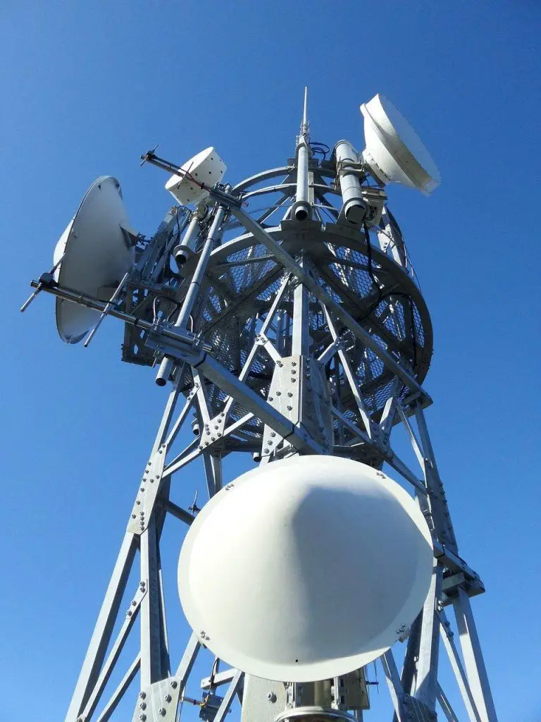
If the line of sight between the two substations appears clear and there are other towers for the signal to hop until it reaches its destination, then install a microwave tower.
The microwave radio signal generated is either
- Analog signal
- Digital signal
Lately, analog microwave radio for transmission protection is being retired and upgraded with the digital one.
Plain old telephone system (POTS)
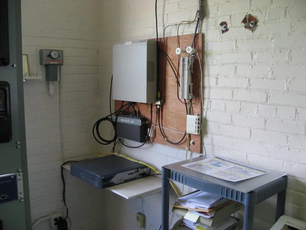
Relay communication may also take place over lines leased from local telephone company.
Much like a power line carrier, protective relays can transmit a tone over the line whose modulation (higher or lower) indicates a fault condition.
POTS facilities utilize either
- Audio tone
- Digital signal
Lately, analog POTS for transmission protection is being retired and replaced in place of other communication technology. Digital service continues to survive because it allows field crews to chat with a load dispatcher, and it maintains 911 service.
Pros and cons of communication channels for pilot relaying
| Communication method | Low latency | Good bandwidth | Low signal attenuation |
|---|---|---|---|
| Power line carrier | X | ||
| Fiber | X | X | X |
| Microwave radio (digital) | X | X | |
| POTS | X |
Ignoring the latency of transmitters and receivers, every communication channel discussed above possesses minimal signal transmission delay. Once the signal gets coupled or transmitted, it travels roughly at the speed of light. For this reason, even something like POTS gets used for direct transfer trip – a high-speed protection scheme.
Low latency is one aspect, but bandwidth is another. Specific protective schemes, like line current differential, require high bandwidth to accommodate significant data flow between relays. Both fiber and digital microwave radio can support this application, unlike PLC and POTS.
No communication channel can elude signal attenuation.
- With PLCs, attenuation may occur due to the corona effect, system disturbances, line switching, storm effects, etc. Attenuation can also occur at the point of coupling as seen in figure 40 in the linked paper.
- With fiber, incorrect splicing, poor terminations, etc. causes light reflection. However, with fewer external factors impacting the signal, this channel stands-out among others.
- With microwave radio, weather condition distorts signal arriving at the receiver.
- With POTS – radio interference, incorrect splicing, poor terminations, etc. diminishes signal.
Transmission line protection schemes employing communication channel
Phase angle comparison
Compares the phase angle of fault current entering and leaving the zone of protection.
If currents are in-phase (entering and leaving the zone), then no tripping occurs on account of the fault being external. However, fault currents 180deg out-of-phase appears internal, and tripping occurs.
Communication channel: PLC, metallic pair, leased telephone line, digital microwave, or fiber optics.
Current differential
Compares magnitude and phase angle of current entering or leaving the zone of protection.
Similar to the phase angle comparison scheme, external faults are ignored whereas internal faults are acted upon.
Communication channel: Fiber optics or digital microwave.
Directional comparison schemes
Works using step distance protection offered by line relays.
To speed up tripping, the following communication/modulation schemes are applied.
- On/Off method
- Directional comparison blocking scheme (DCB)
- Frequency shift keying (FSK) method
- Permissive overreaching transfer trip scheme (POTT)
- Permissive under-reaching transfer trip scheme (PUTT)
- Directional comparison un-blocking scheme (DCUB)
Communication channel: PLC (for DCB & DCUB only), leased telephone line, digital microwave, or fiber optics.
Summary
Personal philosophy, availability of channel, and experience of operating the protected line dictates which protection scheme gets implemented. When a fiber channel exists, the current differential scheme is the obvious choice. Otherwise, existing power lines can be used to administer any one of the directional comparison schemes. Substations located in remote locations can rely on PLC and as a back-up, on microwave radio. As you dig deeper into modulation schemes, you will understand why some cannot be implemented over PLC and must use other channels.
This article is the first in a series, covering the essentials on pilot relaying and pilot protection schemes. If interested, dig deeper below.
- Directional Comparison Blocking Scheme (DCB)
- Permissive Overreaching Transfer Trip Scheme (POTT)
- Directional Comparison Un-Blocking Scheme (DCUB)
- Direct Transfer Trip Scheme (DTT) (This is technically not a pilot scheme but requires a pilot channel)

Great article, learning a ton from you!
Very easy to understand. To the point, no fluff. I like it!
Thanks!
Very good, simple explanation of transmission line relaying, DTT, POTT and DCB.
I love your write up because it’s quick and to the point for those who have some knowledge of the systems, it gives a good overview.