The Directional Comparison Blocking (DCB) scheme is the most popular pilot relaying scheme, implemented to protect high voltage power lines. This scheme is more dependable than a permissive overreaching transfer trip scheme because it trips the breaker even when there is no carrier signal from the remote end pilot relay. Let’s dive into details.
Equipment Needed for Directional Comparison Blocking Scheme
- Inside the control building:
- Distance relay like the Schweitzer 421.
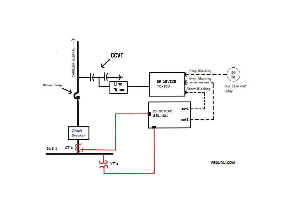
- Pilot relays like Pulsar TC-10B or Ametek’s UPLC-II. They generate carrier frequency.
- Hybrids – either balanced (resistive or reactive) or unbalanced a.k.a. skewed. Hybrids multiplex multiple signals (Tx/Rx) from the carrier equipment onto a single coax wire while minimizing signal distortion.
- Out in the yard:
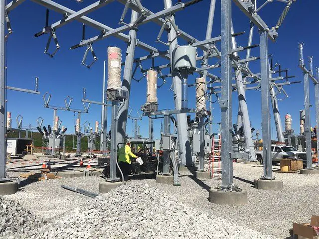
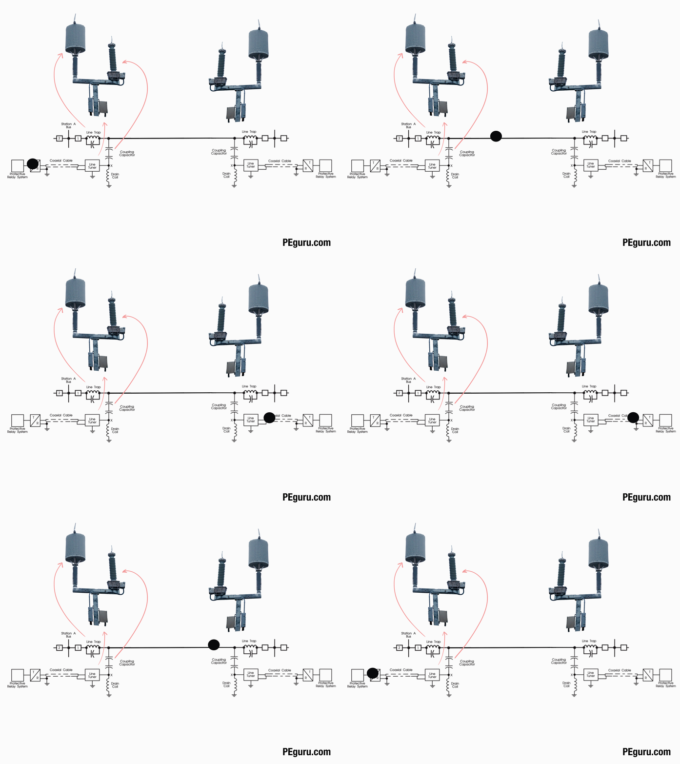
- Line tuner. It’s a bandpass filter. It permits the passage of carrier frequency from the pilot relay on to the transmission line. It also contains an impedance matching transformer so that the carrier signal on a 50ohm coax wire does not reflect due to a transmission line with ~400ohm characteristic impedance.
- Capacitor Coupled Voltage Transformer. This device too provides a path for the carrier frequency, onto the transmission line. The capacitor in this device, combined with the inductance inside the line tuner, creates an RLC resonant circuit. The resonant frequency selected is the same as the carrier frequency.
- Wavetrap. It’s a bandstop or notch filter (made of capacitor and inductor). It limits the carrier signals to the intended line section and prevents its propagation into the substation. Imagine it as a wall that blocks the carrier frequency.

Implementation of Directional Comparison Blocking Scheme
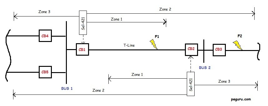
High-speed tripping logic for DCB = Fault in Zone 1 OR Fault in Zone 2 AND no blocking signal received (from zone 3).
Let’s examine the DCB scheme using the figure below and its scenarios.
Fault @ F1 on T-line:
This fault is internal to the circuit breakers CB1 and CB2. These breakers are the closest to the fault, and tripping them will isolate the fault. In this scenario, CB1 and CB2 trip without delay, by SEL-421.
Fault @ F2 on T-line:
This fault is external to CB1 and CB2 but internal to CB3 and its remote end breaker(s). Since (time-delayed) zone 2 protective element on the CB1 relay can trip on it, it should be blocked. The intent is to trip the breakers local to the fault rather than taking out a larger portion of the system.
Thus, while CB3 takes measures to isolate the fault, CB2’s zone 3 element (looking backward) detects this fault as external and keys a “block from tripping” signal to CB1.
Do note that this blocking is not perpetual. The SEL-421 at CB1 is on a time-delayed logic and will eventually trip CB1, thus providing backup to CB3 when it fails to operate.
Fault @ Bus1
CB’s 1, 4, and 5 should trip to isolate the fault on Bus 1. A bus differential relay executes this job via a 86 lockout device. Contact from this 86 relay is also used to engage the 85 device – to key the block signal to remote-end (to stop CB2 from tripping on
The above setup is quite simplified with only one device transmitting the carrier frequency. In practice, you could have 2 devices transmitting or 1-transmitting & 1-receiving or 2-receiving, etc. If you wish to multiplex multiple signals onto a single coax wire then you will need something called the hybrids. Furthermore, there is a very specific way to tie the hybrids (in order to decrease the signal-loss). It is beyond the scope of this article to explain this, however, read this resource (specifically page 27) that goes in great detail.
The distance protection using the DCB scheme is typically used as the first line of defense, especially when the comm channel is the power line carrier. The backup scheme tends to be either POTT or DCUB.
Advantage of Directional Comparison Blocking Scheme
DCB is a dependable scheme because in the event the communication channel gets disrupted, the relays do not sit idle, waiting on the carrier signal. It only needs the channel to transmit a block signal for external faults.
On the flip-side, you wouldn’t know the channel has issues until the system gets activated or gets tested. To check the integrity, a test signal a.k.a. checkback is transmitted 3 or 4 times a day.
This article, part of a series, covers the essentials on pilot relaying and pilot protection schemes. If not done already, start at the beginning.
- Basics of Pilot Relaying & Application Considerations For Transmission Line Protection
- Directional Comparison Blocking Scheme (DCB)
- Permissive Overreaching Transfer Trip Scheme (POTT)
- Directional Comparison Un-Blocking Scheme (DCUB)
- Direct Transfer Trip Scheme (DTT) (This is technically not a pilot scheme but requires a pilot channel)


It is possible to do DCB over fiber?
Any disadvantage(s) for DCB?
I am sorry I assumed that zone 2 under DCB is the same as zone 2 under distance protection , now everything makes sense . Thank you !!!
CB 1 has zone 2
I have two questions for fault F2 on line , why are we blocking the tripping of CB1 , as CB 1 has zone and fault f2 , occurs on zone 1 for CB 3 , CB 3 will go out faster anyways than CB 1 , so why are we doing that ? Second , if should CB3 fails to operate you want CB2 to operate first the breaker nearest to CB 3 , now that being said , it then indeed makes sense to block CB 1 from tripping beacuse , if CB 3 fails CB2 will operate and clear the fault , and CB 1 will be blocked from tripping under zone 2 . So that is my main point of confusion .
Thanks for these information. Finally able to kill my confusions.