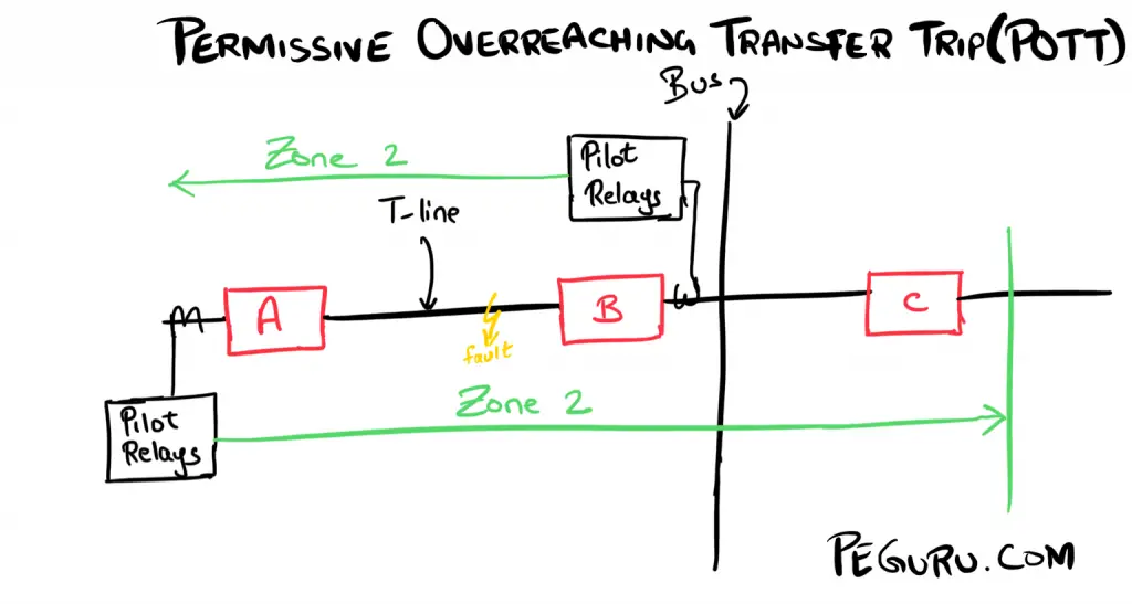
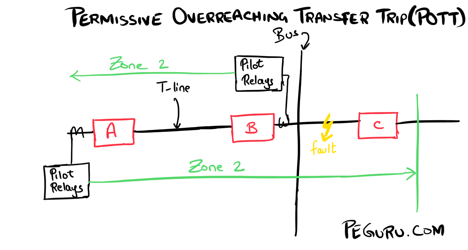
POTT scheme works using the following logic:
High-Speed Tripping Logic for POTT = Fault in Zone 2 AND permission-to-trip signal from remote end relay
POTT Trip Scenario No. 1: Fault in the zone of protection
- A fault on the t-line is picked-up by the zone 2 element of each relay.
- Both relays key permissive signal to each other.
- The relays go ahead and trip their respective breaker A & B.
POTT Trip Scenario No. 2: Fault outside the zone of protection
- The fault is not covered by the relay at breaker B.
- A permissive signal is NOT keyed to breaker A.
- On the flip-side, breaker A relay does pick-up on this fault and transmits the permissive trip signal to the relay at breaker B.
- Based on logic mentioned at the beginning of the article, line relays at breaker A and breaker B will not initiate a trip.
- For this fault location, ideally, the bus differential relay would pickup and trip breakers B and C.
As mentioned above, POTT scheme relies on receiving a “permission to trip” signal from the remote-end relay and the local relay to initiate a breaker trip. The signal is keyed using a Frequency-Shift Keying (FSK) transmitter/receiver (see Ametek TCF-10B).
Under normal conditions, the relay transmits a “guard” frequency. This frequency prevents the relay from operating.
Under abnormal conditions, the relay switches to a higher or a lower frequency to transmit a “trip” signal. When relays on both ends of the line shift to the “trip” frequency, only then are the breakers tripped. The guard/trip frequencies are maintained and specified by the utility such that no two lines in the system use the same frequency.
POTT scheme and Power Line Carrier
Usually, POTT schemes do not get implemented over the power line carrier. A fault on the line may short-out the permissive trip signal, and with the lack of this signal, the relay operation gets inhibited. For this reason, facilities like leased telephone lines, fiber optics, or microwave radio are employed.
If you insist on implementing POTT using PLC then multi-phase coupling of the carrier signal is necessary (i.e. wavetrap, CCVT, tuner, et.al. installed on the 2nd or all 3 phases.) This provides redundancy for the secure operation of this scheme. Another alternative is to use the unblock scheme. The logic is quite similar to POTT with one minor variation.
This article, part of a series, covers the essentials on pilot relaying and pilot protection schemes. If not done already, start at the beginning.
- Basics of Pilot Relaying & Application Considerations For Transmission Line Protection
- Directional Comparison Blocking Scheme (DCB)
- Permissive Overreaching Transfer Trip Scheme (POTT)
- Directional Comparison Un-Blocking Scheme (DCUB)
- Direct Transfer Trip Scheme (DTT) (This is technically not a pilot scheme but requires a pilot channel)


Pingback: Direct Transfer Trip Scheme | PEguru
Post updated based on user feedback
Can you please elaborate?
The explanation only covers the detail of communication signal. A good answer; anyhow, nothing is mentioned about the protection scheme itself. for example, which zone generates the signal and how it is compared on the other side relay